Table of Contents
Scanner
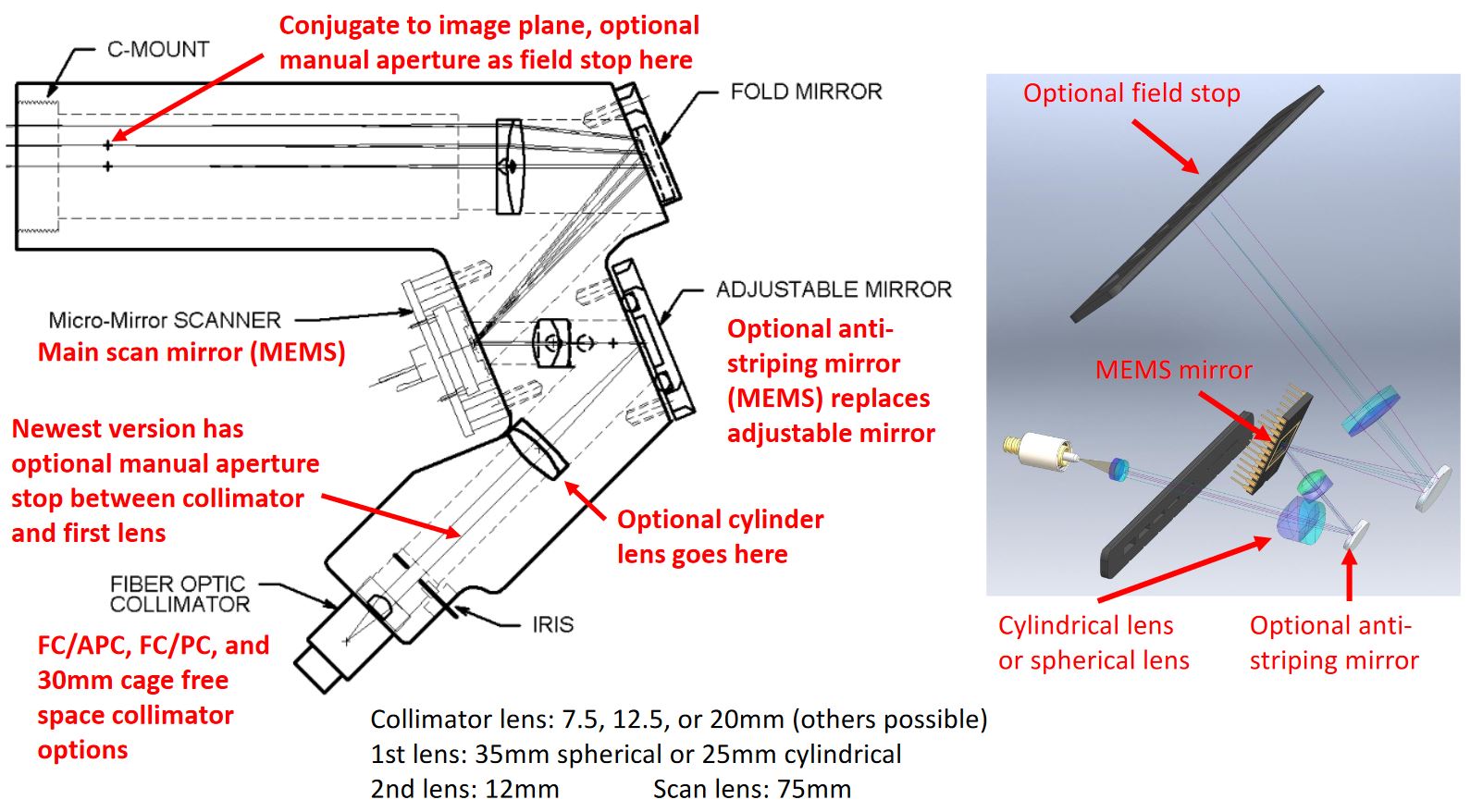
The very initial iSPIM and diSPIM in the Shroff lab used a homebuilt scanner system with galvo. ASI developed a compact fiber-coupled “scanner” that uses a tip/tilt MEMS mirror to move a beam to create a light sheet (patent US10168519B2). One axis of the MEMS mirror is moved rapidly to create a virtual light sheet – usually one pass across the camera sensor per image – and the other axis of the MEMS mirror is adjusted to keep the light sheet plane coincident with the detection objective's focal plane. ASI provides control electronics for the scanner that go in the its modular TG-1000 controller
Several scanner variants exist including versions with a cylinder lens for fixed sheet, a version based on ASI's C60-CUBE-III, and a version with a fancy scan lens (the latter two are better choices for applications where it's important to fill the BFP, in contrast with typical light sheet with low-NA beams and where some field curvature of the scan lens can be easily tolerated). The standard scanner has provision to add an optional anti-striping mirror, but this option is rarely used.
An iris is used as an aperture stop – i.e. to control the beam NA and hence sheet thickness and confocal length (see page on Gaussian beams). There is an option to motorize this iris in the standard scanner body, which is convenient in multi-user situations or where the scanner is not easily accessible due to incubation equipment. Furthermore, there is provision for a slider with apertures to be introduced instead of using an iris; these are especially handy for scanners with cylindrical lenes where it is desirable to aperture the beam in one axis and not the other.
Most often a fiber collimator (with FC/PC or FC/APC interface) is used to couple the excitation beam into the scanner, but free-space coupling is possible. A tunable lens can be added between the fiber collimator and the scanner to allow for electronically-controlled focal position along the propagation axis at the sample.
The output is C-mount threads that easily attach to an ASI tube lens (i.e. the scan lens is an integral part of the scanner itself). In order to scan the beam exactly parallel to itself 4f spacing needs to be maintained between the MEMS mirror and the sample, meaning that the spacing between the scanner tube lens and objective back focal plane needs to be correct.
A schematic of the standard ASI scanner: (PDF).
Cylinder Lens vs. Scanned Beam
The light sheet scanner body can accommodate a cylindrical lens to make a stationary light sheet. The external appearance is identical. The same physical microscope can be either a scanned (digital) system or a static sheet system by changing out the scanner.
The advantages of the cylindrical lens version include:
- faster imaging speed is possible (e.g. by ~2x) because you don't have to blank the beam during camera readout and beam flyback
- cost $5k less each (beam scanning subject to non-ASI patent which we collect royalty fee for)
- for many samples bleaching will be less by spreading out photon dose over longer time, ditto for avoiding fluorophore saturation
The disadvantages of the cylindrical lens version include:
- can't use the virtual slit trick for partial confocality
- no stroboscopic effect to minimize motion blur
- Gaussian intensity profile of illumination intensity across field ⇒ may need flat field correction
MEMS limitations
The resonance of a typical (1.2mm dia.) MEMS mirror is on the order of 2.5kHz, you have to stay far away from that or else the mirror can self-destruct. So 1kHz is the approximate upper bandwidth. How fast you can realistically make a light sheet is several times smaller and depends on the size of the sheet and whether you “fly back” and make all sheets in the same direction (default) or not. There is a lowpass filter in the electronics that can be set (by default to 400Hz).
A good rule of thumb with standard objectives is that both the scan and max flyback can keep up with the camera readout speed but not go too much faster. E.g. with 512 rows the readout time is 2.5ms and we can do a 2.5ms scan and flyback in 2.5ms for 200fps.
Larger MEMS mirrors are available and may be useful to achieve higher illumination NA when required. However, the larger mirrors usually have a lower resonance so cannot be driven as fast.
An arcane optical effect called “bow” that occurs when the axis of rotation isn't orthogonal to the plane made by the incoming/outgoing beams. Since we have a 2D mirror, only one of the rotation axes can be made perpendicular to the beam plane and the other axis unavoidably suffers from this bow problem. The resulting effect is a slight optical coupling of the axes, on the order of a few percent over the entire mirror travel for a standard scanner. The Tiger controller firmware compensates for the effect automatically in internal mode and a per-axis compensation factor can be set (ERROR command). With a cylindrical lens, the “ideal” axis can be either the line axis (allowing you to perfectly smear out the Gaussian intensity profile within the plane) or else the slice axis (allowing you to move the light sheet to create a stack in piezo/slice synchronous scan mode without tilting the light sheet), but not both simultaneously. This has to be set in the factory during scanner assembly, and unless otherwise specified the latter option is chosen, which also corresponds to having the cylindrical lens scanner oriented in exactly the same manner as a Gaussian beam scanner.
