Table of Contents
Dated Hardware
Piezos
The method for inserting the objectives was significantly improved in the piezo objective mover (POM) mounting scheme introduced in early 2015. The main benefit is easier objective alignment due to the replacement of the AOA objective adjuster with a smooth linear stage, but other notable benefits include:
- installing objectives no longer requires disassembling a SPIM arm,
- piezos easily slide out of the arm for easy exchange and cleaning of objectives,
- the linear adjuster is fixed instead of being moved by the piezo, improving speed slightly,
- and bushings include teflon glides to keep them snug.
ASI offers upgrades to the new mounting scheme at cost.
Care of piezo objective movers
In general, unnecessary electronic and mechanical stresses on any type of piezo should be avoided. Electronically speaking, being left in positions near the edge of their travel range or being left on (powered) for extended periods of time will cause them to wear out faster. Mechanically, for pre-2015 POMs in particular, care must be taken when screwing in the objective bushings as they can put stress on the piezo top plate (outward). Please refer to the hardware page on Piezos for more details on piezo care.
Install the objectives on pre-2015 piezos
Because of the geometrical constraints inherent in having the two objectives so closely mounted together and the need to minimize mechanical stress on the piezos, one of the POMs should be loosened from it’s mount on the SPIM arm. In order to accomplish this, one SPIM arm (components 8-12 in Figure 1 in the diSPIM Manual) should be removed in order to access the screws (indicated by red arrows in Figure 1) connecting the POM to the arm mount.
To install objectives on pre-2015 piezos,
- Detach the scanner’s electrical and fiber optic cable, if attached.
- Position the bushing; nominal spacing between the objective bushing and piezo is ~5 mm. 1)
- Loosen the three set screws (indicated by a yellow arrow in Figure 1) connecting the arm mount to the bottom cube on the side that does not have an objective mounted.
- Pull slightly on the SPIM arm to disengage the support dowel between the lower cube and the arm mount, as in Figure 2. Gently set it aside.
- Loosen the 4 screws mounting the POM, as in Figure 3. It is optional but usually unnecessary to fully remove the POM assembly.
- Insert the objective on the opposite side, i.e. the side that still has the SPIM arm connected.
- Install the second objective, taking care that you do not apply unnecessary stress on the piezo.
- Tighten the screws holding the POM/objective assembly to the SPIM arm mounting plate.
- Reattach the SPIM arm.
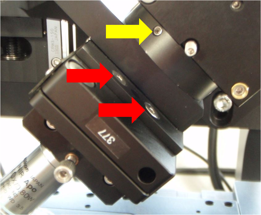 Figure 1: Before screwing in your objective, detach the SPIM arm via the set screws (indicated by a yellow arrow) so you can access all the screws that mount the POM (indicated by red arrows)
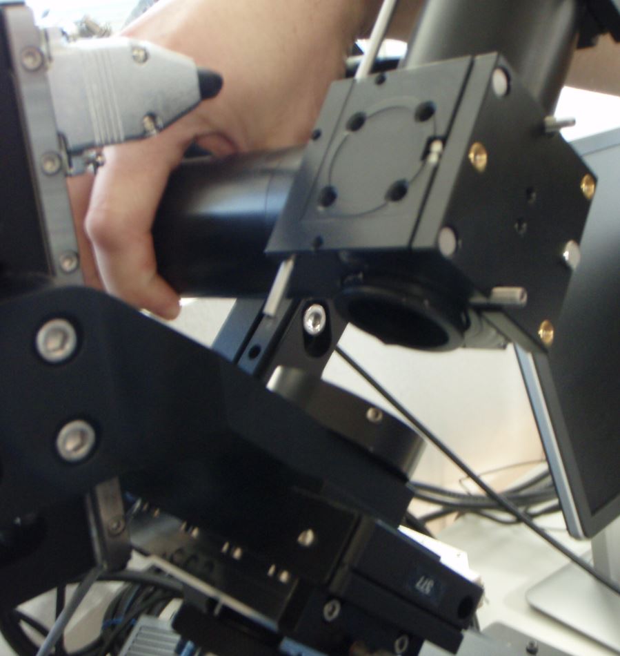 Figure 2: Separate the SPIM arm from the mount
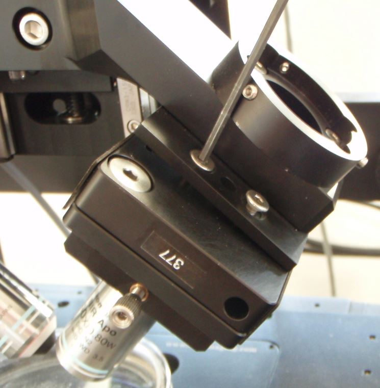 Figure 3: Loosen the screws holding the POM to the SPIM arm mount
Use the bushings and objective adjusters shown in Figure 4, Figure 5, Figure 6, Figure 7 to move the objectives until they are visually symmetric from the front of the microscope, as shown in Figure 8, and aligned front to back as well. Avoid using the vertical objective position adjuster (Figure 7) after the objectives have been aligned by eye. Make sure the vertical adjuster screw is not loose but also not so tight that lateral adjustment is impossible. Because the lateral and vertical position adjusters are coupled, you may need to work the screws against each other.
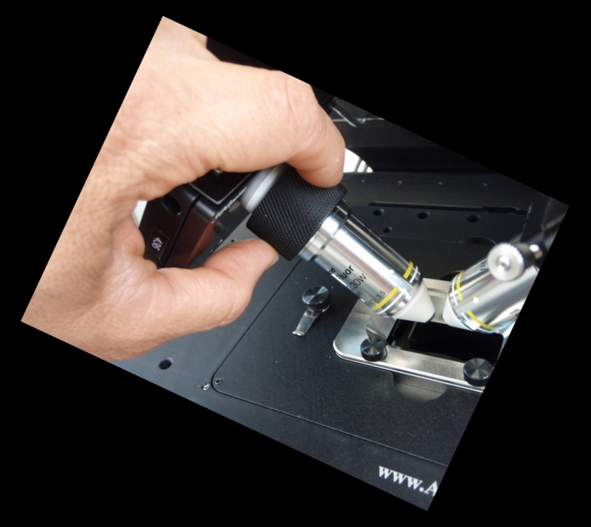 Figure 4: Left objective focus bushing
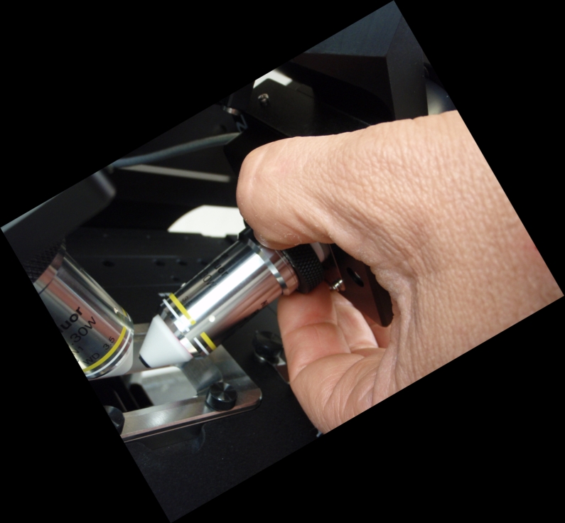 Figure 5: Right objective focus bushing
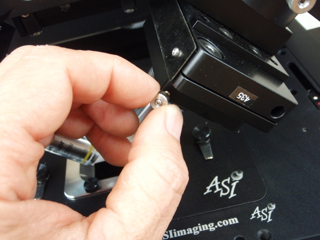 Figure 6: Lateral objective adjustment screw; the vertical objective position adjuster
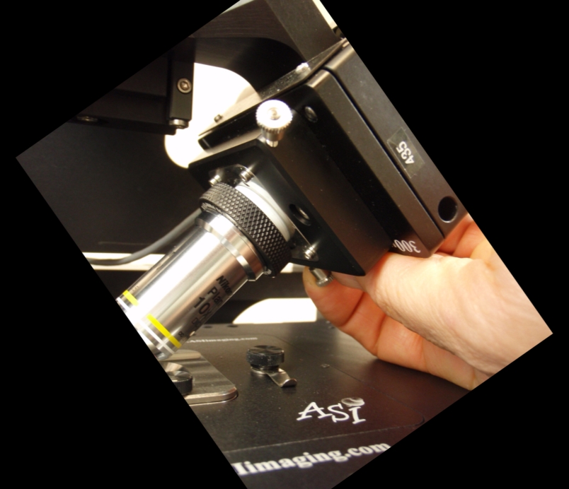 Figure 7: The vertical objective position adjuster is used to lower the objective when changing lenses; its effects are similar to the left objective focus bushing, and hence redundant
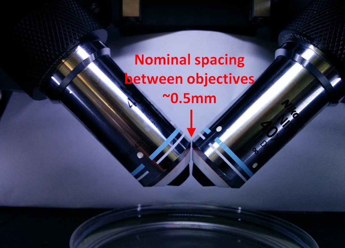 Figure 8: Nikon 40x, 0.8 NA, 3.5 mm WD objectives co-focused with ~0.5 mm gap
Stage Scanning
SPIM systems 2016 or later should be good to go on stage scanning. If you have an earlier system you should verify the following if you have any trouble with stage scanning:
- An ASI-made XY stage, whether on a RAMM or other inverted microscope (requires tight synchronization of the stage with the light sheet/laser/camera). In mid 2016 ASI transitioned to “scan-optimized” stages with SPIM systems; these stages have 16 TPI leadscrews for a slower overall motion (and hence better accuracy with slow moves) and omit the anti-backlash gearing on the X axis for smoothest possible scanning.
- “SCAN” firmware module on XY card in the Tiger controller
- Use SCAN_XY_LED firmware variant on the XY card; this has been in the firmware releases for download (on this page above) since late 2015.
- As of June 2018 there are two firmware versions available and flash the one that matches your stage. Use SCAN_XY_LED_SOAdr1.hex for scan-optimized 16 TPI stages (note the “SO”) or SCAN_XY_LEDAdr1.hex for 4 TPI stages.
- All firmware should be updated to v3.10 or later
- XY card Rev F2 or later with proper jumper (standard after Jun 2015) http://dispim.org/_media/hardware/stage_scan_xy_jumper.png
- Micromirror card with proper jumper (standard after Jun 2015)
- For micro-mirror card Rev E3 or later, add this jumper as in the photo at http://dispim.org/_media/hardware/stage_scan_micromirror_jumper.png
- For micro-mirror card Rev C, it is similar to Rev E3 except the order of that bank of 8 jumper positions is reversed. So for Rev C leave the top position in the bank vacant and fill all the other positions, which means adding a jumper in the 3rd position from the top.
- Software support (present in Micro-Manager plugin since mid-2015)
TTL Card
The “TTL Card” was the predecessor to the PLC card now used in Tiger Controllers.
If you have a TTL card, use
- CAM0: camera trigger for Path A
- CAM1: camera trigger for Path A
- LSR0: laser on/off control
- LSR1: laser side select.
LSR0 and LSR1 may be connected differently if you have a non-standard laser configuration. For control of multiple laser lines, the PLC card is required. Contact ASI if you need more information.