Table of Contents
Controller
The diSPIM uses ASI's modular controller, the TG-1000 or “Tiger” controller. It has separate cards for controlling the XY stage, linear stages, micro-mirrors (scanners), triggering cameras/lasers, driving piezo objective movers if present, driving filterwheels if present, etc.
Firmware
In general firmware updates add new functionality and fix bugs while retaining backwards compatibility, though on rare occasion backward compatibility is compromised. If you are not using Micro-Manager, you should double-check with the vendor of the acquisition software before updating firmware. If you are using Micro-Manager, you should generally download the latest nightly build whenever you update firmware. Conversely, if you are having problems with a recent build of Micro-Manager make sure that the controller firmware is the latest.
Warning: these instructions are for iSPIM and diSPIM only. If you have another type of ASI light sheet microscope (e.g. oSPIM or single-objective light sheet) contact ASI for guidance and for the proper firmware files.
Before you begin
Updating the firmware will erase all (or very nearly all) the firmware settings, including the positions of motorized axes, software-defined limits, axis speeds, etc. Move motorized stages to their zero position if feasible, or at least to a known position so the zero position can be easily recovered. Turrets and filter sliders, if any, should be moved to their first position. If you have made adjustments to firmware settings outside of the diSPIM plugin it is advisable to note them down so that you can set them again afterwards. This is not necessary for settings controlled by the diSPIM plugin.
Required software and instructions
To update the firmware you need the ASI Tiger Console software and the latest diSPIM firmware package from ASI (dated 2024-08-21, firmware version 3.45), or from the diSPIM firmware archive. Use 7zip to decompress. This firmware should work for diSPIM systems sold 2014 or later. A link to download firmware for the oSPIM is found on the oSPIM page.
General instructions for using the ASI Tiger Console software for updating the firmware are here.
Standard firmwares for card addresses on diSPIM controllers are as follows. Omit any cards that your controller doesn't have. Almost always you will be programming the same firmware build name as exists on your current controller and you can see the list if you are connected via serial to the controller when it powers up or else by issuing the WHO command. If your controller is otherwise non-standard (e.g. the addresses don't match the labels on the front of the controller) feel free to contact ASI for help.
| Address | Card | Usual Firmware | Comments |
|---|---|---|---|
| 0/30 | Comm card | TigerComm | |
| 1/31 | XY stage | SCAN_XY_LED_SO__Adr1 (16 TPI stages) | SCAN_XY_LED__Adr1 for 4TPI stages, “SO” version for scan-optimized stages which have been standard from mid-2016 on |
| 2/32 | Z/F stages | STD_ZF_LED__Adr2 | STD_ZF__Adr2 if no LED being used, FTP_ZF if you have an FTP system (XYZ stage) instead of inverted microscope |
| 3/33 | Micromirror | MMIRROR_SPIM__ABCD_Adr3 | |
| 4/34 | Piezo P | ADEPT_SPIM__P_Adr4 | |
| 5/35 | Piezo Q | ADEPT_SPIM__Q_Adr5 | |
| 6/36 | Progr. Logic | PLOGIC_16__E_Adr6 | |
| 7/37 | Mot. Iris | IRIS__TU_Adr7 |
In general you should update all the firmware on your controller together. One exception is filter wheel firmware which generally does not need updating.
If you have any trouble please contact ASI.
Extra step with pre-3.20 XY stage firmware
In late 2016 ASI transitioned to using scan-optimized XY stages with SPIM systems by default. These stages have 16 TPI leadscrews instead of the usual 4 TPI leadscrew, along with removing anti-backlash gearing in the X axis for smoother scanning.
As of firmware version 3.20 (June 2018) there are two firmware versions available for the XY card and you should use the one that matches your stage. Use SCAN_XY_LED_SO__Adr1.hex for scan-optimized 16 TPI stages (note the “SO”) or SCAN_XY_LED__Adr1.hex for 4 TPI stages.
Using firmware prior to v3.20, after flashing the XY card firmware you need to set the leadscrew pitch using a serial command if you have a scan-optimized stage. That way the controller knows that the leadscrew pitch is 16 TPI and can report distances accordingly. Unless told otherwise the firmware assumes 4 TPI leadscrew.
To tell the firmware about the leadscrew pitch you send a single serial command to the controller. In Micro-Manager you can use the property “SerialCommand” of the TigerCommHub device or you can use some other program, both methods are described in ASI's serial communication documentation. Send the serial command, then turn off the controller before doing anything else. After powering the controller back on verify that the setting registered. If you are using Micro-manager you will need to shut it down and restart as well. For 16 TPI leadscrews use the following command: (others can be found in the ASI documentation)
1 CCA X=6
Extra step with pre-3.00 piezo firmware
If you are upgrading from pre-3.00 firmware then the piezo range(s) may need to be set to match the hardware using the PR command. Starting with firmware version 3.00 the piezo range is stored in a way not affected by firmware updates.
To set the piezo range you need to send serial commands to the controller using a serial program. In Micro-Manager you can use the properties “SerialCommand” and “SerialResponse” of the TigerCommHub device, or you can use another program as described in ASI's serial communication documentation. Send the PR command with the appropriate range code followed by the SS Z command for each affected card so that the setting to save the settings to non-volatile memory. For example, the most common configuration is 150um range piezos (range code 3) on axes P and Q which are on cards 4 and 5. For this, send the following commands:
PR P=3 Q=3
4 SS Z
5 SS Z
Afterwards power cycle the controller and verify the setting took effect. You can see the current range in Micro-Manager with the read-only property “PiezoTravelRange(um)”, or send PR <axis letter>? and look at the reply code. Common range codes are 3 for 150um, 4 for 200um, and 5 for 300um piezo range.
Programmable Logic Card (PLC)
The Programmable Logic Card (PLC) is a field-programmable card for digital logic, sort of a mini-FPGA inside the Tiger controller. Its original use is to enable multi-laser control for diSPIM, but it is designed to be very flexible. You can find full documentation of the PLC on the ASI website.
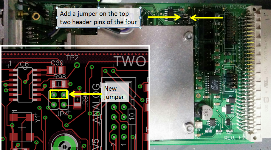
When used for diSPIM under Micro-Manager, the PLC uses a clock signal from the micro-mirror card so that the camera and laser triggers are tightly synchronized with the sheet generation. For Tiger controllers sold with the PLC this is already done, but when the PLC is added to an existing controller a jumper must be added to the micro-mirror card as shown in this photo.
Stage Scanning
Instead of moving the sheet position and imaging piezo to create a stack of images, the sample can be translated through a fixed sheet. Generally speaking this is best for large and/or flat samples.
The main advantages of stage scanning are that the light sheet can be thinner for flat samples because the beam waist stays at the same height relative to the coverslip and that the “Z-stack” is limited only by the travel of the X-axis of the stage (instead of the piezo range). The main disadvantages are that the output data need to be deskewed or sheared before conventional analysis and the minimum time between time points is somewhat longer than with a piezo. (Typically the stage is plenty fast for acquisition, i.e. the acquisition is camera/photon limited, but the motorized stage can't return to its starting position as fast as a piezo stage). Users of static light sheets should also address PSF-blurring resulting from stage scanning; Nyquist demands >2 images per stationary PSF, but motion blur requires you to sample more.1) The swept beam of a digital light sheet produces a “stop motion” effect and therefore does not require increased sampling.
In the usual implementation, the stage moves continuously in the X axis at an appropriate rate to give the user-specified slice spacing. The speed of the scan optimized stages is very uniform (see hardware notes below) and the stage's encoder triggers the acquisition internally to give extremely repeatable positioning of repeated stacks.
Requirements for Stage Scanning
If you have a SPIM system 2016 or later you should be good to go. If you have an earlier system you should verify the following if you have any trouble with stage scanning:
- An ASI-made XY stage, whether on a RAMM or other inverted microscope (requires tight synchronization of the stage with the light sheet/laser/camera). In mid 2016 ASI transitioned to “scan-optimized” stages with SPIM systems; these stages have 16 TPI leadscrews for a slower overall motion (and hence better accuracy with slow moves) and omit the anti-backlash gearing on the X axis for smoothest possible scanning.
- “SCAN” firmware module on XY card in the Tiger controller
- Use SCAN_XY_LED firmware variant on the XY card; this has been in the firmware releases for download (on this page above) since late 2015.
- As of June 2018 there are two firmware versions available and flash the one that matches your stage. Use SCAN_XY_LED_SO__Adr1.hex for scan-optimized 16 TPI stages (note the “SO”) or SCAN_XY_LED__Adr1.hex for 4 TPI stages.
- All firmware should be updated to v3.10 or later
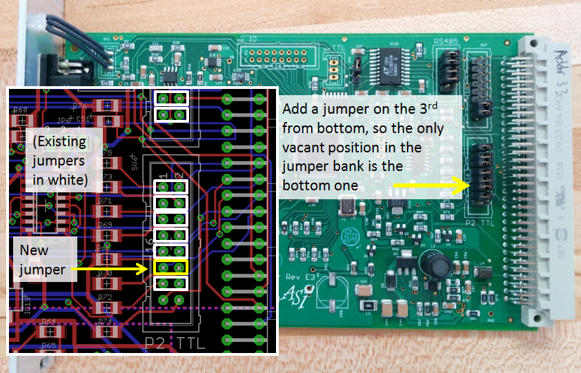
- XY card Rev F2 or later with proper jumper (standard after Jun 2015)
- Make sure the following jumper is present: this photo
- Micromirror card with proper jumper (standard after Jun 2015)
- For micro-mirror card Rev E3 or later, add this jumper: this photo
- For micro-mirror card Rev C, it is similar to Rev E3 except the order of that bank of 8 jumper positions is reversed. So for Rev C leave the top position in the bank vacant and fill all the other positions, which means adding a jumper in the 3rd position from the top.
- Software support (present in Micro-Manager plugin since mid-2015)
Hardware Notes
- The stage cannot go arbitrarily slow and still be perfectly smooth. ASI's standard “scan optimized” stages use 16 TPI leadscrews that have a max speed of ~1.75 mm/s and a speed setting quantum of 172 nm/s. To a fair approximation, the slowest speed that is relatively smooth is ~1000x slower than the max speed or about 12x the quantum. So the “minimum smooth” speed is 1.8 um/sec for 16 TPI leadscrews.
Post-Processing Notes
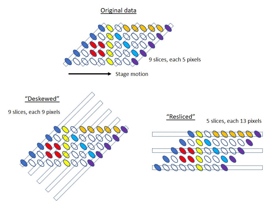
- As noted above the data needs to be deskewed before it can be used/viewed in a conventional way. On-the-fly deskewing for visualizing test acquisitions and also for post-processing real acquisitions is in the plugin as of December 2016; the algorithm is fundamentally the same as the ImageJ macro but hopefully easier to use because the metadata provides most parameters (but background correction must be performed separately).
- Unfortunately deskewing can blow up the size of (uncompressed) data files because a lot of empty space is added.
- An alternative to deskewing is reslicing. This can be as simple as reshuffling pixels in memory if the stage translation speed is chosen to be an integer number of pixels. Reslicing along the stage direction spreads the optical low-resolution between 2 axes but reduces the empty regions created by deskewing, particularly for long stage-scan stacks. The following diagram hopefully helps:
- It would be highly desirable for analysis and viewing software to be able to handle the deskew operation in memory and on the fly. To date the only software known with this capability is FIJI's Big Data Viewer. Lobby your favorite software provider for this and make life better for everyone (many light sheet microscopes including lattice light sheet also require the same deskew step).
- Micro-Manager 2.0 has a helpful ability to reslice data (an “Image Processor” added mid-2023) which is helpful especially for stage scanning data. The GPU version of the algorithm can operate on datasets up to 1/4 of the GPU memory, e.g. 2 GB datasets can be processed on a GPU with 8 GB of working memory. The GPU version does interpolation and the CPU version is faster but doesn't do any interpolation.

Micro-Manager Implementation Notes
- The spacing between slices is specified in the plugin, so the stage moves sqrt(2) times that distance per slice for 45 degree geometry (the actual angle can be set as of March 2018). There may be very small rounding errors (which would come out in normal post-processing) but the metadata should contain the actual slice spacing instead of the user-specified one. Rounding errors were reduced as of the 2018-03-15 nightly build.
- The initial X position is used as the center X position of the dataset and the stage should return there afterwards.
- For large samples there is a YZ grid creator (as of March 2018) so multiple strips can be collected covering a sample. The same GUI allows you to create a “grid” in X where instead of specifying slice spacing you specify start, stop, and number of slices.
- There are three modes implemented, “stage scan”, “stage scan interleaved”, and “stage scan unidirectional”; see the manual's description of the different SPIM acquisition modes.