This is an old revision of the document!
Table of Contents
Micro-Manager diSPIM Plugin User Guide
The diSPIM plugin adds functionality to Micro-Manager from alignment to acquisition. This user guide gives an introduction to the utility of each of the tabbed panels in the plugin, as well as guidance on hardware- and sample-based considerations.
If you are not familiar with Micro-Manager, please read the User Guide and Configuration Guide before running the plugin. Also, refer to the diSPIM manual: Getting started with Micro-Manager for guidance before aligning your diSPIM.
Before running the diSPIM plugin, create or load a Micro-Manager hardware configuration with all the relevant devices. The plugin is accessed through the Micro-Manager menu bar: Plugins > Device Control > ASI diSPIM. The plugin has 10 tabbed panels for different features and tasks. After opening the plugin, first configure the Devices Tab. Keep the main Micro-Manager window accessible; the plugin generally does not duplicate functionality already provided there. In addition to the tabbed panels, a sidebar provides a color coded “quick glance” indication of each axis’ position:
- Gray = no device
- Green = centered
- Orange = near center
- Red = far from center
- Pink = making sheet (scanner only)
- Black = beam turned off (scanner only)
Devices Tab
Use the Devices tab to assign hardware roles in order to gain access to the plugin’s features; re-visit this tab if you change hardware configurations in Micro-Manager or if you launch the plugin without the devices loaded.
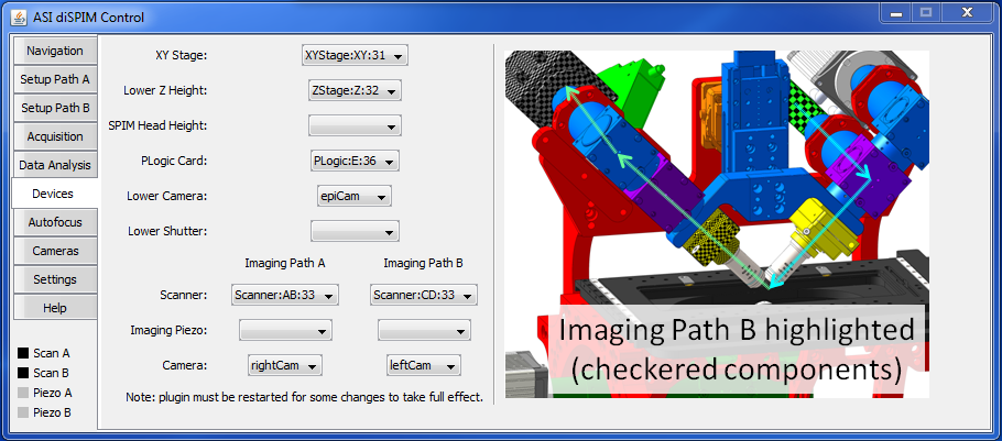 Figure 1: The Devices tab in the diSPIM plugin must be configured; give special care to properly match the assignment with the physical hardware, especially regarding scanners and piezos.
For a diSPIM mounted on non-ASI inverted microscope frames, the Lower Z Height device may or may not work, dependent on Micro-Manager support. The imaging paths are the two possible light paths. For each path, the scanner is on one side, and the imaging piezo and camera are on the opposite side. In ASI’s typical controller configuration,
- The Lower Z Height is the lower Z stage: Z-axis, associated with the inverted scope.
- The SPIM Head Height is the upper Z stage: F-axis.
- Imaging Path A is the left scanner with axes A and B, right-side (imaging) piezo with axis P, and the right-side camera. 1)
- Imaging Path B is the right-side scanner with axes C and D, left (imaging) piezo with axis Q, and the left-side camera. Imaging Path B is the checkered components in Figure 26.
For a single-sided system (iSPIM), leave the Imaging Path B devices blank.
Setup Path Tabs
There are two setup tabs, one for each imaging path. These tabs are essential during diSPIM alignment. They are also used to set the center position of the imaging piezo (and by extension the center of the imaged 3D volume). For a single-sided system (iSPIM), ignore the Setup Path B tab.
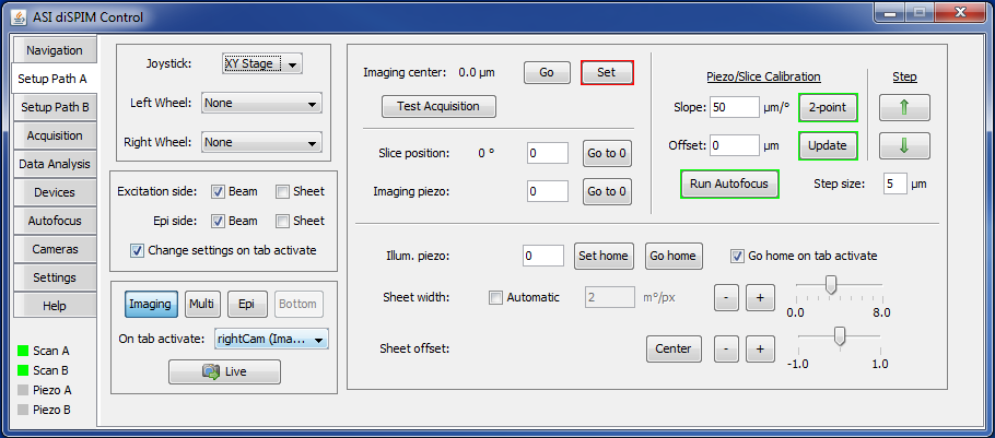 Figure 2: The settings on the Setup tabs immediately apply upon tab activation.
Tab-specific: controller, beams, cameras
Each Setup tab has an independent set of tab-specific controls: joystick/wheel, beams/sheets, and cameras; e.g. the joystick can control different devices on the different Setup tabs. The joystick/wheel control settings automatically become active when you click into the tab; you can opt for the same functionality with the beam/sheet selection via checkbox. (The beam control uses the scanner “blanking” feature; it assumes that both scanners have input light, e.g. a passive splitter between the laser and the scanner.) Unless No change is selected from the camera control On tab activate drop-down menu, the camera will automatically be set to the specified camera when the tab is selected.
Similar controls exist on the Navigation tab.
Imaging piezo: center and calibration
The center position for the imaging piezo is displayed, and the Set button sets the current position as the new center. This setting is crucial for acquisitions, but can be ignored during alignment. The up and down arrow buttons on the right move the piezo and slice together according to the calibration relationship. The amount of piezo travel per button click is set by the step size. This is useful for checking whether the calibration relationship is correct, and also for moving through the object of interest to confirm acquisition settings are correct.
Position display and sheet control
The position of the slice is shown, along with the positions of the imaging and illumination piezos. Use the text entry boxes to move the axis to a specific position. For single-sided operation, there is not an illumination-side piezo. For diSPIM, the illumination piezo has a “home” position during illumination (recall that the imaging piezo will be moving along with the slice position). The illumination piezo will go to the home position when the tab is selected if the Go home on tab activate checkbox is checked. The sheet width and sheet offset affect the sheet dimensions and center position. The + and - buttons are for fine adjustments; the sliders are easier to use for large changes.
Setting piezo/slice calibration
After fine alignment of the microscope is complete, the scanner movement in the slice direction needs to be cross-calibrated with the imaging piezo in order to remain coincident. During acquisition, the piezo and slice will move together through the sample to create a stack of images. Both the piezo objective movers and micromirror-based scanners have decent intrinsic linearity, so it suffices to identify two distinct locations where the light sheet is in focus and compute the relationship between the scanner position and imaging piezo. The computed values can be manually tweaked if desired. The autofocus can find the focus when doing the 2-point calibration or else updating just the offset. See the section on the Autofocus tab for more information.
Setting the calibration start and end positions goes quickly if the system is well-aligned:
- Introduce a fluorescent dye or bead sample.
- Make sure the sheet is in focus (i.e. that the imaging piezo is in a good position) and that the upper Z stage:F-axis and illumination piezo are in good positions as well.
- Move the imaging piezo to what will be approximately one end of the image. For example, if you are imaging an object that is 100 um across (and the imaging center is close to zero), move the imaging piezo to 50 um by manually entering the imaging piezo’s position.
- Use a joystick knob to move the scanner’s slice position until the beam is in focus. In a dye solution this is easiest when the sheet is turned off; with a bead slide it is easiest when the sheet is turned on. If you are already close, you can use the Run Autofocus button to adjust the slice position.
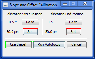
- Click the red-bordered Set button under “Calibration Start Position”.2)
- Move the imaging piezo to the other end of the imaging piezo’s normal range, e.g. -50 um for this example.
- Use the joystick knob or autofocus to move the scanner’s slice position again until the beam is in focus.
- Click the red-bordered Set button under “Calibration End Position”.
- Click the Go to buttons for both start and stop to make sure that the imaging piezo and scanner’s slice position are correct (i.e. beam in focus) at both points.
- Click the green-bordered Use these! button to compute the slope and offset of the calibration relationship.
- Check the computed calibration using the up and down arrows in the upper right of the Setup tab (you may need to increase the step size).
Generally the calibration slope will remain relatively constant but the offset can change slightly. It is easy to update the offset without changing the slope (e.g. when introducing a new sample):
- Move to a central part of the sample.
- Click the Run Autofocus button. The system will attempt to move either the piezo or slice position to the best focus depending on options in the Autofocus tab. Alternatively, use the joystick knob to move the scanner’s slice position and/or the imaging piezo's position until the slice is in focus.
- When focus looks good, click the Update button next to the offset value on the Setup to adjust the calibration so that the current in focus position is now on the calibration line.
Light Sheet Synchronization
When the cameras’ acquisition trigger mode (on the Cameras tab) is set to utilize light sheet mode, settings will appear for light sheet synchronization: synchronizing the beam with the rolling shutter of the camera. These settings replace the usual sheet width and offset adjustments.
Light sheet synchronization is achieved by adjusting the speed and starting point of the sweeping beam3). These settings are exposed to the user as a slope parameter (speed) and offset parameter (starting point) in the bottom of the setup panel. At present the parameters need to be tuned manually. In the future hopefully there will be a semi-automated way of doing this tuning, much as there is a semi-automated way of performing the slice/piezo calibration using autofocus. For adjustments in the ROI, the slope parameter may need to be slightly tweaked. The offset parameter is sensitive to the exact lateral position of the objective so it may need to be tuned slightly daily, similar to the offset of the piezo/slice calibration.
The beam must remain horizontal across its entire scan range in order to utilize light sheet mode. This requires having a 4f configuration of lenses so that the tilt of the scanner's mirror is a pure translation in the image plane with no residual tilt. The spacer between the lower CUBE-III and the scanner tube lens can be used to achieve this spacing. For the Nikon 40x/0.8 objective, a 10 mm spacer is about right; many existing systems have either 7.5 or 15 mm spacers which may be satisfactory for small fields of view. Contact ASI if you need a different size spacer, or if you would like to upgrade/exchange for a continuously-adjustable spacer. Take an iterative approach to tuning the light sheet synchronization parameters:
- Align the system if it isn't already aligned.
- Use a very uniform sample, e.g. dye in solution.
- Set the start/offset parameter to 0. This will be relatively close to the final value.
- While in live mode adjust the speed/slope parameter until the sheet exactly fills the field of view. This will be relatively close to the final value.
- Run a test acquisition. Consider setting the acquisition mode to “No scan (fixed sheet)”. You should get images with some fluorescence. If only a short horizontal bright stripe appears then add a minus sign to the speed/slope parameter to invert the direction of the beam scanning.
- Iteratively tune the two parameters by finding a best setting for one, adjusting the other, and so forth until you have zeroed in on the best setting. In each case the tuning procedure is to run a test acquisition, evaluate the results, and adjust the parameter again until you find the best setting where changing the setting in either direction gives worse results.
- For the speed/slope parameter:
- Start with ~3% changes to the parameter and work down to <1% changes.
- Try to maximize uniformity of sample brightness from top to bottom of the acquired images (it helps to have a perfectly uniform sample). If the speed of the beam is not the same as the speed of the rolling shutter there will be a brighter band when one passes the other. Your goal is to make the two speeds equal by tuning this parameter.
- You can conveniently visualize the uniformity using ImageJ: Edit > Options > Profile Plot Options… and click the Vertical Profile checkbox. Make a rectangular ROI selection on your image, and then Analyze > Plot Profile. You want the profile to be approximately level, not with a distinct peak.
- For the start/offset parameter:
- Changes should be ~3% of the speed/slope value at first, working down to changes <1% of the speed/slope value.
- Try to maximize the brightness of the sheet in the acquired images (it helps to have a perfectly uniform sample). If there is some constant offset of the beam from the rolling shutter the acquired image will be dimmer than if they are exactly coincident. Make the two coincident by tuning this parameter.
- You can conveniently visualize the average intensity again by using ImageJ's plot profile, histogram, or measure commands.
Note that Micro-Manager's live mode won't work properly with “light sheet” camera operation because it requires tight synchronization between the beam and the camera shutter. In live mode, the camera is free-running. Perhaps in the future the plugin will implement some sort of pseudo-live mode.
Navigation Tab
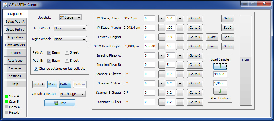
The Navigation tab (Figure 4) allows the user to easily view and change the position of all ten diSPIM axes. By default positions are updated once per second (see also Settings tab). As with the Setup tab, there are tab-specific joystick, beam, and camera controls.
The left column of text entry boxes moves the respective axis to a specific position. The next column of text entry boxes (between the minus and plus buttons) specifies the increment that the buttons will move that axis with each click.
A button is provided to move each axis to the zero position. It is very useful to move the upper and lower Z axes to the imaging position and click their Set 0 buttons so they can return to that position with a single button click.
Finally, clicking the Halt button will send a command to the Tiger controller to stop the movement of all axes; this is mainly to prevent an imminent crash.
Autofocus Tab
The diSPIM plugin can leverage software autofocus routines that are already part of Micro-Manager to facilitate setting the piezo/slice calibration. The autofocus can also be set to run periodically during acquisition to counter any focus drift.
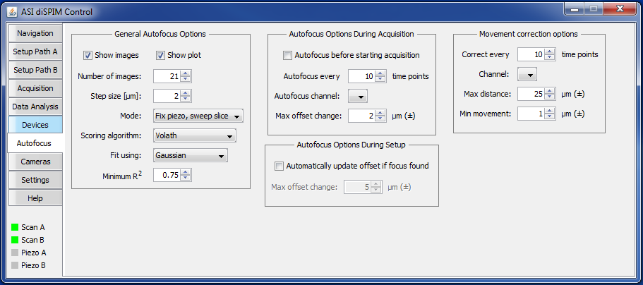 Figure 5: The Autofocus panel offers options on scoring algorithm, timing, and movement.
The autofocus works by taking a stack of images (sweeping either the piezo or slice while keeping the other fixed) and then evaluating each image according to a focus scoring algorithm. Multiple such algorithms are built into Micro-Manager already. The position vs. fit score is plotted and fit to a curve, e.g. Gaussian, and the optimal position is determined by the maximum of the fit curve. Furthermore, the R^2 value of the fit is determined. If the R^2 value exceeds the minimum value set and the optimal position is within the center 80% of the sweep range then the swept axis is set to the optimal position. It is up to the user to verify that this position is appropriate and update the calibration offset or set this as an input point for the 2-point (slope) calibration.
Cameras Tab
The Region of Interest and camera triggering mode is specified in the Cameras tab. For Andor Zyla and Hamamatsu Flash4 cameras there is the possibility to have consecutive triggers determine the start and end of a image capture; this is termed respectively “Overlap” and “Synchronous” by the manufacturers but referred to uniformly as “Overlap” in the plugin. Because the image sensor is simultaneously read out and reset to begin the subsequent exposure, the camera overhead time is reduced and it allows for faster camera frame rates.8). The downside is that there can be slight “ghosting” or bleedthrough from frame to frame because the reset isn't quite complete. The same mode is not available with the PCO.edge or Photometrics Prime 95B. However, a new exposure can begin shortly after the readout starts which is a mode we refer to as “Pseudo Overlap”.
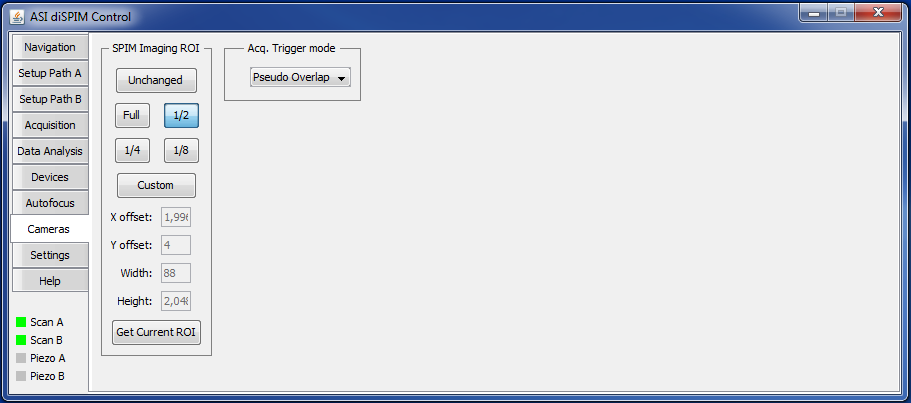 Figure 6: The Cameras panel allows you to set the ROI and the acquisition trigger mode.
Settings Tab
The Settings tab (Figure 7) hosts options about the GUI, scanner, stage scanning, and more.
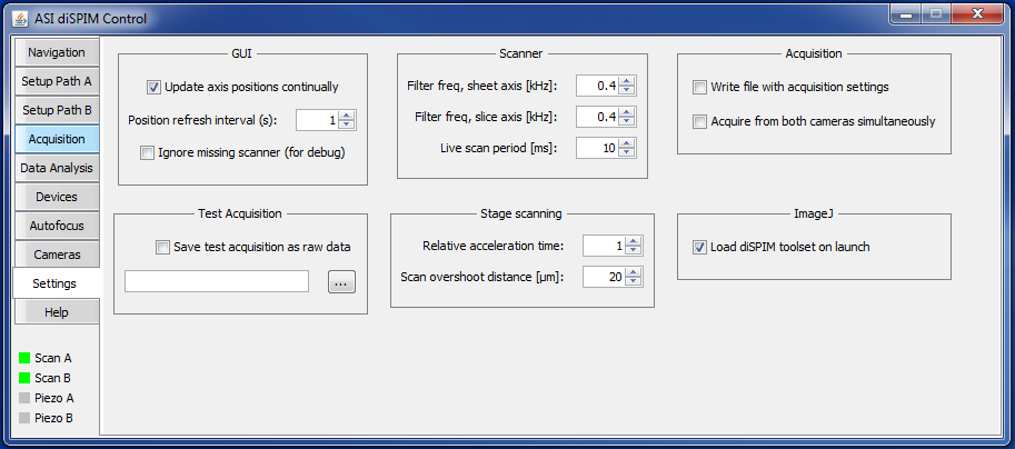 Figure 7: The Settings panel contains various settings not belonging elsewhere.
GUI settings affect the axis positions displayed on the Navigation tab.
The scanner (micromirror) drive card has adjustable Bessel output filters to protect the filter from being driven near its mechanical resonance (usually 2 kHz). Settings as high as 0.8 kHz are usually acceptable, and in general the shorter the scan period (and faster frame rates) the more this matters.
Acquisition Tab
In the Acquisition tab, shown in Figure 8, you set the parameters for and initiate the SPIM acquisition. This panel is analogous to the Multi-D acquisition window in Micro-Manager, except that the positions of the imaged volume are not specified here. By default, the joystick and wheels are disabled, but clicking the checkbox enables the joystick settings as set on the Navigation panel.
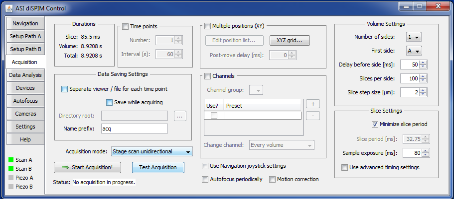 Figure 8: The Acquisition tab has advanced timing settings disabled in this image.
Setting the 3D ROI
Use the Setup tabs to specify the center slice position and other volume settings. The number of slices per side and the slice step size determine how far on each side of the center position is imaged.
Use Micro-Manager’s usual mechanism to specify the ROI of the two SPIM cameras; see the Micro-Manager User's Guide on ROI.
Durations
The time required for acquiring each slice, a single volume (one or two sided), and the total acquisition is displayed in the “Durations” box in the upper left.4)
Time Points
If you click the checkbox for Time points, you can specify the number of time points and the interval between them. Under most circumstances the plugin actually triggers separate single-volume acquisitions in the controller so that the exact moment when a time point starts is controlled by the PC which presumably has a very accurate time source.
If the time between finishing one time point and starting the next is less than 0.75 seconds, a special “hardware timepoints” mode is invoked silently; the controller takes charge, and the spacing between time points may not be quite as accurate.
Data Saving Settings
Specify where and how the data is saved.
- Separate viewer / file for each time point: performs a separate Micro-Manager acquisition for each time point, implying a separate viewer window and separate file. In general it is better to let Micro-Manager save all time points to a single file.
- Save while acquiring: saves the data to disk; if unchecked then data will be saved in RAM and the user will have the option to save it later. Obviously, for large acquisitions the data must be saved to disk directly.
Acquisition Mode
Currently several modes are supported:
- Synchronous piezo/slice scan: standard use, the piezo and sheet move together through the sample
- No scan (fixed sheet): neither the piezo nor light sheet moves; useful for characterizing vibration in the system
- Stage scan: uses the XY stage to move the sample through a fixed light sheet; for two-sided acquisitions, one view is collected in the first pass, and the second view is collected as the stage moves “back” for a second pass; see the document on stage scanning for details and requirements
- Stage scan interleaved: same as stage scan except that the stage moves half as fast and the two light paths alternate, meaning both views are collected in the same pass; use caution if you are using a galvo to switch the laser between the sides, this can overstress some galvos
- Stage scan unidirectional: same as stage scan except the second view is taken while scanning in the same direction as the first view with a rewind step between. For 1-sided acquisitions stage scan and stage scan unidirectional are equivalent. For 2-sided acquisitions the stage scan unidirectional will take slightly longer (the rewind step is done at 75% of the max stage speed) but makes data processing easier.
- Slice scan only: suppresses movement of piezo but moves the light sheet; useful for characterizing light sheet thickness
- Piezo scan only: the light sheet stays stationary but the piezo moves; useful for establishing axial PSF
Acquire Button
Click the Start Acquisition! button to start or abort an acquisition. The status string informs you which time point is being acquired.
Multiple Positions (XY)
If the box is checked, the plugin will use Micro-Manager’s position list to acquire volumes and multiple locations. For each time point, every position is visited once. See Micro-Manager User’s Guide for more details on the Position List Dialog.
For large samples there is a YZ grid creator (as of March 2018) so multiple strips can be collected covering a sample. Open the grid creator window by clicking on the “XYZ grid…” button. Select the axes that you want to create the grid in and click the “Compute grid” button to set up the grid. You can mark specific start/stop positions in live mode. The delta for Y and Z can be entered manually, or if you click the button “Set” next to those fields then the value is populated based on the camera ROI and the overlap percentage setting. Note that the X axis is used for stage scanning, so when you create a “grid” in X you are specifying start and stop positions and spacing between them in stage coordinates.
Overview Acquisition
As of March 2019 there is a feature to acquire an overview acquisition. This is useful when the entire sample is many times larger than the instantaneous field of view. The overview image is a 2D image representing a thin slice of the sample which can be collected relatively quickly. After acquisition, a rectangle is placed on the overview image representing the current stage position, and this rectangle moves with the stage as long as positions are being updated. It is not intended for use with a Z grid but only XY grid.
Settings for the overview acquisition reside on the “Data Analysis” tab. These include the downsample factor for XY and for slice spacing. The fractional thickness specifies how much of the entire image will be max projected to form the overview image. You specify a channel and a side to run the overview acquisition with.
Perform the overview acquisition using the button in the “XYZ grid…” window accessed from the acquisition tab. Running the acquisition uses the current settings of the grid GUI for X and Y (if they are enabled) and will overwrite any existing position list.
Channels
The channels feature is patterned after that of Micro-Manager’s Multi-Dimensional Acquisition). It is most commonly used to take volumes with different illumination wavelengths (e.g. 488 nm and 561 nm for samples labeled with GFP and mCherry). Before using this feature, you must create and configure a group of presets containing the settings for that channel. Simple per-volume channel switching is implemented unless a Programmable Logic Card (PLC) is present in the controller; this mode is generic and can be used with any Micro-Manager group. PLC-based channel switching is hardware-based, requiring extra setup time but then no delay during acquisition. Using the PLC, channel switching is possible on both a per-volume and per-slice basis. In this case the channel group must contain the property “Output Channel” which is used to select the correct laser to trigger; other properties in the channel group, if any, are ignored.
Volume Settings
Use the parameters in the “Volume Settings” group to set up the stacks to be collected:
- Number of sides: 2 for diSPIM, 1 for single-view
- First side: whether Path A or Path B goes first
- Delay before side: wait period after initiating the side (moving the illumination objective and imaging piezo into position) before beginning stack acquisition; when stage scanning, this is the stage speed settling time to ensure uniform speed
- Slices per side: number of frames to acquire on each side
- Slice step size: increment of imaging piezo (and light sheet will follow) for each slice, i.e. the Z-stack step size; for stage scanning this is the orthogonal spacing between slices, i.e. if this is 1 um then the stage will move 1.41 um between slices 5)
Exploring Resolution and Z-step Size
Distinguishing two nearby point sources of light is a classic problem in optics. If a camera’s pixels are so large that both points are read by the same pixel, you won't be able to tell them apart, regardless of how good the optics. The camera resolution must be at least twice the optical resolution to avoid being the limiting factor; essentially, a dark pixel must be between the two bright pixels. This is a manifestation of the Nyquist sampling theorem, which describes a fundamental mathematical relationship between continuous (or analog) and discrete (or digital) signals. The standard formula for the optical lateral resolution is the Rayleigh criterion, a distance given by the formula: 0.61*lambda/NA (where lambda is the wavelength of light). For a 40X 0.8NA objective with 500 nm light, the lateral resolution is ~381 nm. That objective with a camera sensor that has a 6.5 um pixel pitch, is spatially sampling at (6.5 um/40X) ~162.5 nm pixel size, so we meet the Nyquist criteria (because 381 nm/162.5 nm = 2.34), but we wouldn't if we were using 400 nm light. Normally, for axial resolution limited by optics, the Z-axis step must be smaller than twice (per Nyquist) the optical axial resolution. Optical axial resolution, or depth of field, is usually taken to be lambda/(NA^2); for the 40X 0.8NA objective at 500 nm, it is ~781 nm. Therefore, the Z-step should be <0.39 nm. For diSPIM, we have two views that can be merged computationally. The axial perspective from each objective is a lateral perspective (with higher resolution) from the other, so we can undersample in Z to a certain extent, which is advantageous from a speed perspective. However, giving up too much axial resolution the registration of the two views will suffer; in an extreme case your Z-step could be large enough to completely skip over a point source. For this reason, we recommend the Z-step be at least as small as the objective's depth of field. (With Fiji MVR and bead datasets, it's easy to register datasets with 0.5 um Z-step spacing but not with 1 um Z-step spacing.)
Slice Settings
- Minimize slice period: when checked the plugin will have zero added delay between slices
- Slice period: requested period of each slice, if not minimized; must be a multiple of 0.25 ms
- Sample exposure: requested illumination time; must be a multiple of 0.25 milliseconds.
- Use advanced timing settings: when the checkbox is checked, settings can be edited directly in a pop-up window; use this if you want to adjust the values that the plugin computes
Slice Settings for Light Sheet Mode
When the cameras are being used in light sheet mode the normal slice settings are not relevant and a different group of settings appear.
- Scan reset time: time for the beam to retrace to the starting position between slices; 3 ms is a good starting value
- Scan settle time: time that the beam scans before reaching ROI, useful to settle to constant speed; 1 ms is a good starting value
- Shutter width: width of the open camera shutter in microns; adjusts the amount of confocality and hence the rejection of scattered light; publications often recommend setting this to 1.5 or 2 times the beam thickness (which can be defined multiple ways); the narrower the shutter the more precise the light sheet synchronization settings need to be.
- Use advanced timing settings: when the checkbox is checked, settings can be edited directly in a pop-up window; use this if you want to adjust the values that the plugin computes
Default Timing
Specify the Sample exposure [ms] in Slice Settings, and either define the slice period or let the plugin minimize the slice period automatically. The timing depends on the reset and readout time of the cameras; plugin code specific to each supported camera computes timings for the user-specified ROI using information provided by the manufacturer (usually either via their detailed camera documentation or read-only Micro-Manager properties). Any extra time in the slice is placed before the camera trigger to allow maximum time for piezo settling. The values computed by the default timing mode are shown in the slice timing settings and can be subsequently modified manually.
Exploring Default Timing
Only one line scan per slice is used. Each period consists of camera readout time, then any extra delay time, camera reset time, and lastly beam scan time. During beam scan time, the laser is off for the first and last 0.25 ms of the scan and on otherwise. Because the beam scan is limited to increments of 1 ms, the laser exposure time must be a half-integer number of milliseconds. An empirical scanner delay according to its Bessel filter is included (so the scan signal is shifted slightly earlier). Times are rounded to the nearest 0.25 ms, except the camera readout and reset times which are always rounded up to the next multiple of 0.25 ms because they are computed according to manufacturer’s timing information and the ROI; they try to account for worst-case jitter. The camera readout time is set to zero if the “Overlap” on “Synchronous” mode of the cameras is used.
Advanced Timing Settings
The detailed controller timing settings are hidden by default but can be accessed by checking Use advanced timing settings checkbox. The vast majority of users will not need to use these. The default timing mode calculates timing parameters from the camera readout mode, ROI, and user-set parameters. The times must all be multiples of 0.25 ms. The advanced timing settings have correspondence to controller settings as follows:
- Delay before scan: time before scan begins (gives piezo stages time to move/settle before sheet acquisition is started) (NV X)
- Line scans per slice: how many one-way beam scans per slice (NR X)
- Line scan duration: time for one sweep of the beam (SAF <axis>)
- Delay before laser: delay before laser trigger is fired (NV R)
- Laser trig duration: duration of the laser trigger (RT R)
- Delay before camera: delay before camera trigger is fired (NV T)
- Camera trig duration: duration of camera trigger (RT T)
- Camera exposure: duration the camera shutter is open
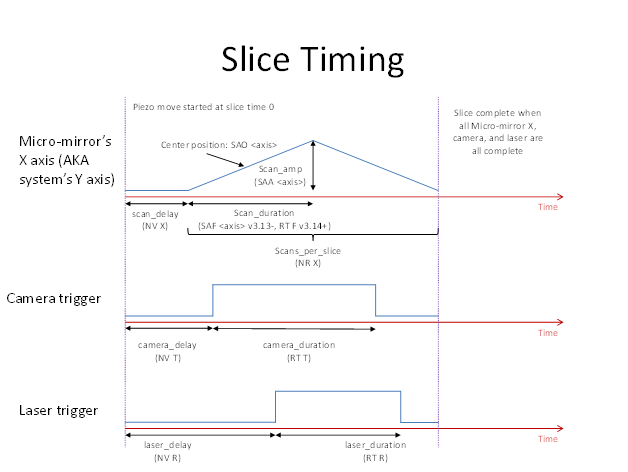 Figure 9: The slice timing involves the piezo, micro-mirror, camera, and laser.
Data Analysis Tab
In the future we would like to include the ability to manipulate the acquired data, including registration of the two views and joint deconvolution, directly in the diSPIM plugin. At present, the Data analysis tab, (Figure 10), exports the acquired data to the format required by the MIPAV GenerateFusion plugin. Fiji’s Multiview Registration plugin can directly import diSPIM data. Exporting operates on the top-most image window.
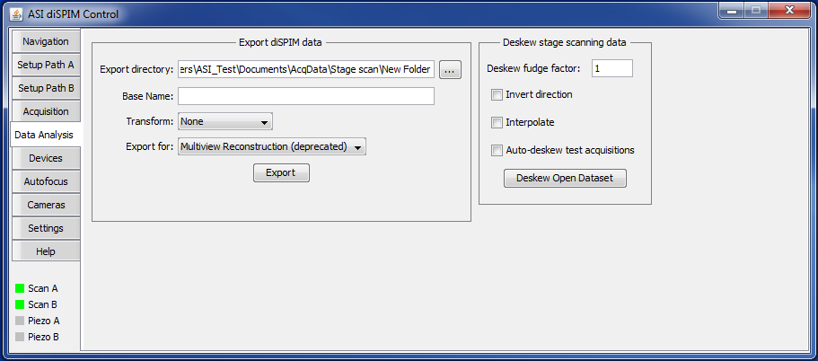 Figure 10: The Data Analysis panel facilitates exporting acquisition data.
Based on the angle specified on the settings tab “Path A stage/objective angle”, the pixel size defined in Micro-Manager’s “Pixel Size Calibration”, and slice spacing then the plugin runs the deskew. If empirically it is off, check the “Invert direction” checkbox and try again. Deskew fudge factor is an additional scale factor on the deskew and should generally be 1.
