This is an old revision of the document!
Table of Contents
diSPIM Alignment
Overview
Before acquiring data the optical paths of the diSPIM must be aligned. This is the trickiest thing for new diSPIM users to learn. If the system is not disturbed then the alignment can last for months. Changing objectives, crashes, filter changes, and so forth will usually require at least partial realignment.
Think of the process of aligning the diSPIM as a giant inward spiral. There are lots of different adjustments to be made, and you will adjust the same thing multiple times as you spiral inward to the perfect alignment. First do a coarse mechanical alignment step using your eye and simple mechanical tools. Next, use the cameras imaging a solution of dye and finally a coverslip with beads to zero in on the perfect alignment.
The scanners are aligned at the factory and are likely to be suitable to use without further adjustment. One of the first checks is to verify that they are indeed not terribly mis-aligned before proceeding with other steps. If the scanners fail this initial check, they should be removed and aligned on the bench using the methods described in Section [sec:Align-the-Scanners].
Ideal final alignment
Below follows a suggested alignment procedure. However, if you achieve good alignment by following some other means that is OK. Here are characteristics of the final alignment you are looking for, which apply to both optical paths of the diSPIM:
- epi spot centered on epi camera
- beam waist centered on imaging camera
- beam/sheet plane coincident with imaging focus plane near the center of the piezo travel
- beam perpendicular to camera field of view
- sheet centered in camera field of view
- sheet centers in center of bottom camera’s field of view (i.e. co-alignment of SPIM objectives with bottom objective)
Beam position and angle: what affects what?
We are concerned with getting both the beam position and angle correct in the sample. Fortunately, the adjustments to do so are mostly “orthogonal” or independent of each other. The following table can be derived by understanding the lens system from the fiber input of the scanner to the sample and then through the imaging path to the corresponding camera on the opposite side of the microscope. Table 1 shows how various “knobs” affect the beam position and angle.
| Adjustment | Position? | Angle? | Comments |
|---|---|---|---|
| Tilt of dichroic mirror | Some | Yes | Position effect varies 1) |
| Tilt of camera mirror | Yes | No | Set during scanner alignment and not after |
| Position of upper Z stage | No | No | Angle varies if scanners are not connected to dichroic tubes |
| Tilt of adjustable mirror | Some | Yes | Set during scanner alignment and not after |
| Tilt of main micro-mirror | Yes | No | Set during scanner alignment and not after |
Coarse Alignment
The following coarse alignment steps are done by eye so that the beams are easily found in the SPIM cameras for the fine alignment.
Co-align the SPIM objectives
Double-check that the SPIM objectives are approximately aligned as described in Section [sub:Insert-the-objectives-2014].
Check rotation of cameras and scanners
Verify that the cameras and scanners are parallel/perpendicular to the SPIM arm cubes as best as possible by eye. Adjust the angles of the devices at their C-mounts as required. With careful sighting along parallel surfaces you can be sure the scanners and cameras are aligned with the rest of the SPIM system to better than 1 degree of rotation. In the long run this will save time having to re-do alignment steps later.
Check course scanner alignment
Warning: be very careful with exposed laser beams; wear appropriate eye protection. Remove the dichroic filter cube assembly (Figure ##) and place the square alignment target shown in Figure [fi:square_target] over the cube opening. Be sure that the scan mirror is not being deflected (turn the controller off to be sure), power on the laser, and observe where the laser spot is hitting the target. If the laser spot is well within the first target ring, proceed to the next steps, otherwise proceed to complete scanner alignment in Section [sec:Align-the-Scanners].
Note that it is possible for the scanners to be misaligned in a way that passes this simple test. If in doubt, contact ASI for help.
Adjust dichroic mirror tilt
Re-install the dichroic mirrors so the laser will be reflected into the objective. With upper Z stage (SPIM objectives) raised, tilt the dichroic mirrors in the adjustable cubes (items 9 in Figure [fi:DiSPIM]) as described in Section [sub:Adjusting-the-Mirror] so that the laser exits the objectives in a straight line. One trick is to use a 45 degree surface like a folded business card or part of a C60-D-CUBE with a piece of paper, as shown in Figure [fig:Scanner-mirror-and]. Use the cube mirror adjusters to adjust the tilt of the filter cube as described in Section [sub:Adjusting-the-Mirror] so that the beam exits the objectives in a straight line.2) This is a course adjustment only, you will return to adjusting the beam pointing using the cameras later.
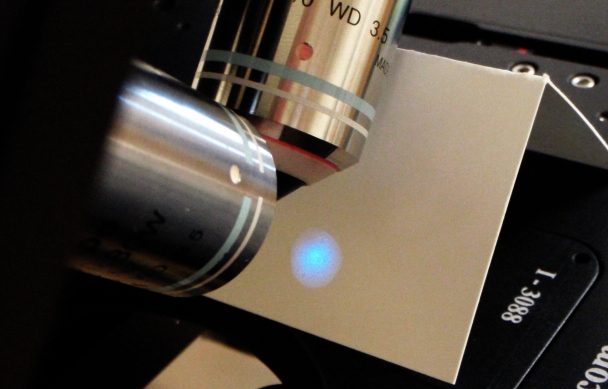 Figure 1: Scanner mirror and iris diaphragm are imaged by the laser on a target in the far-field of the objective. The emerging beam is adjusted to be centered leaving the objective.
Check scanner beam centering
Check the centering of the scanners since it is easy to do at this point. You should be able to see the extent of the scanner mirror with the scanner iris fully open. See Figure [fig:Scanner-mirror-and]. The center of the Gaussian beam, the center of the iris aperture, and the center of the scan mirror should all be approximately concentric. In practice this is hard to achieve perfectly. If you are not satisfied, proceed to Section [sec:Align-the-Scanners] to improve the situation, or contact ASI for assistance.
Fine alignment
For the rest of the alignment we will use the SPIM cameras. The following steps may need to be repeated several times in an alternating fashion until the alignment is complete. It is recommended to first get each alignment relatively close, proceed with the rest of the alignment steps, and then come back to each step to finish; in other words go around the “alignment spiral” a few times not worrying about perfection at first. It is easiest to perform the fine alignment in a dye solution (water with a dip of Highlighter pen works well, or a dye like fluorescein). The final steps can also be performed with a 2D sample of fluorescent beads.
You will need Micro-Manager running to have a live view of the camera images. It is helpful to set a relatively long exposure time for the cameras, e.g. 100 ms. Launch Micro-Manager, the diSPIM plugin, and configure the plugin as described in Sections [sub:Before-Running-the-plugin] and [sub:Devices-Tab]. You will use the Navigation panel (Section [sub:Navigation-Tab]) extensively, as well as the two Setup panels (Section [sub:Setup-Tabs]).
Co-align the SPIM objectives
Use only three adjusters to manipulate the focus and relative beam positions, the two objective threaded bushings for focus, and the lateral objective position adjuster. See Figure [fig:Three-orthogonal-objective]. Bring the beams into focus with the imaging objective bushing threads. Alternate between adjusting the two bushings and only move half way to the focus at a time (before alternating sides) to achieve convergence even if there is a bit of play in the objective bushings.
Overlay the images from both cameras using the MultiCam feature and move the lateral adjustment to place the red beam on the red spot, and green beam on green spot. Figure [fig:Co-aligning-objectives] illustrates the procedure. Alternate between the steering adjustment and focus adjustment. If it seems impossible to get a uniform pencil beam, realize that the desired parallel beam might tip it quite far from your current focus point. Go for uniform width first, then focus. As a last resort, see section [sub:Adjust-scanner-slice-offset] to rectify this.
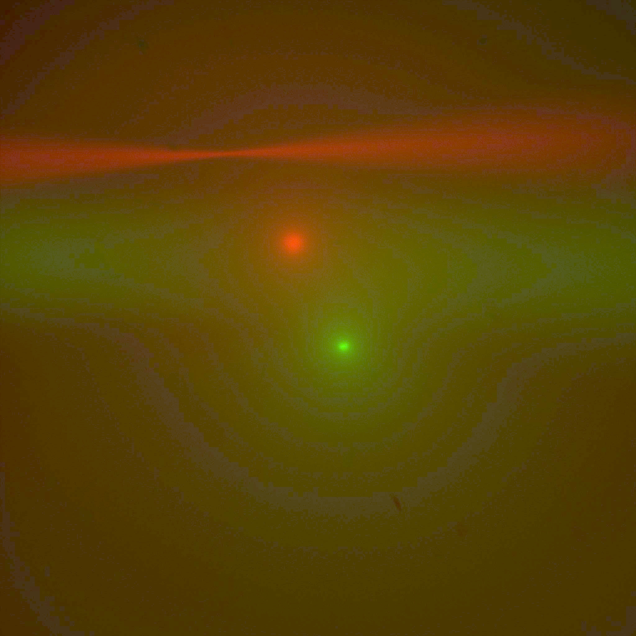 Figure 2: Co-aligning objectives, starting out with both beams and epi-spots, nothing very well aligned.
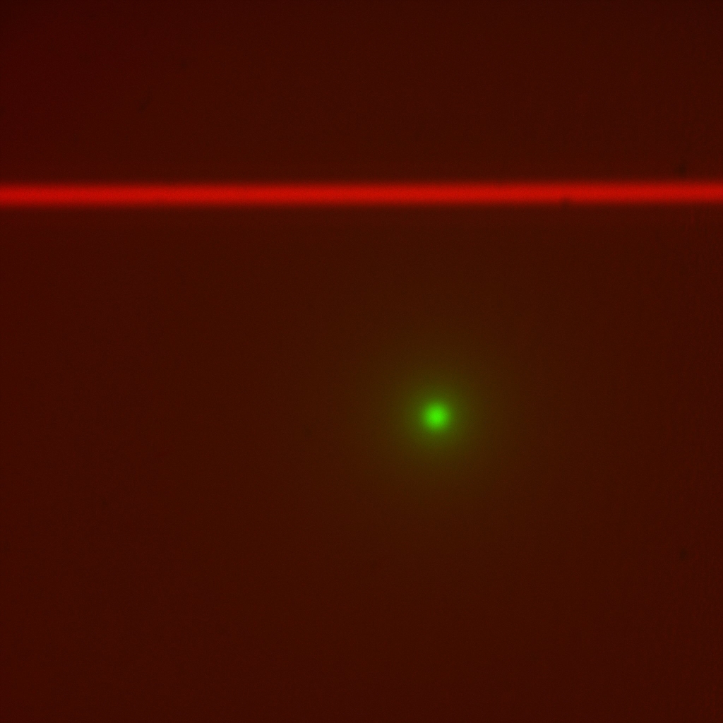 Figure 3: Look at red beam only with scanner iris closed down all the way so laser is a “pencil beam.” Use adjustment
screws on the scanner’s dichroic mirror holder to make the pencil beam straight horizontally and
in focus along the beam. Adjust imaging objective bushing focus as necessary to keep the beam in focus as you
make changes to the beam steering adjusters.
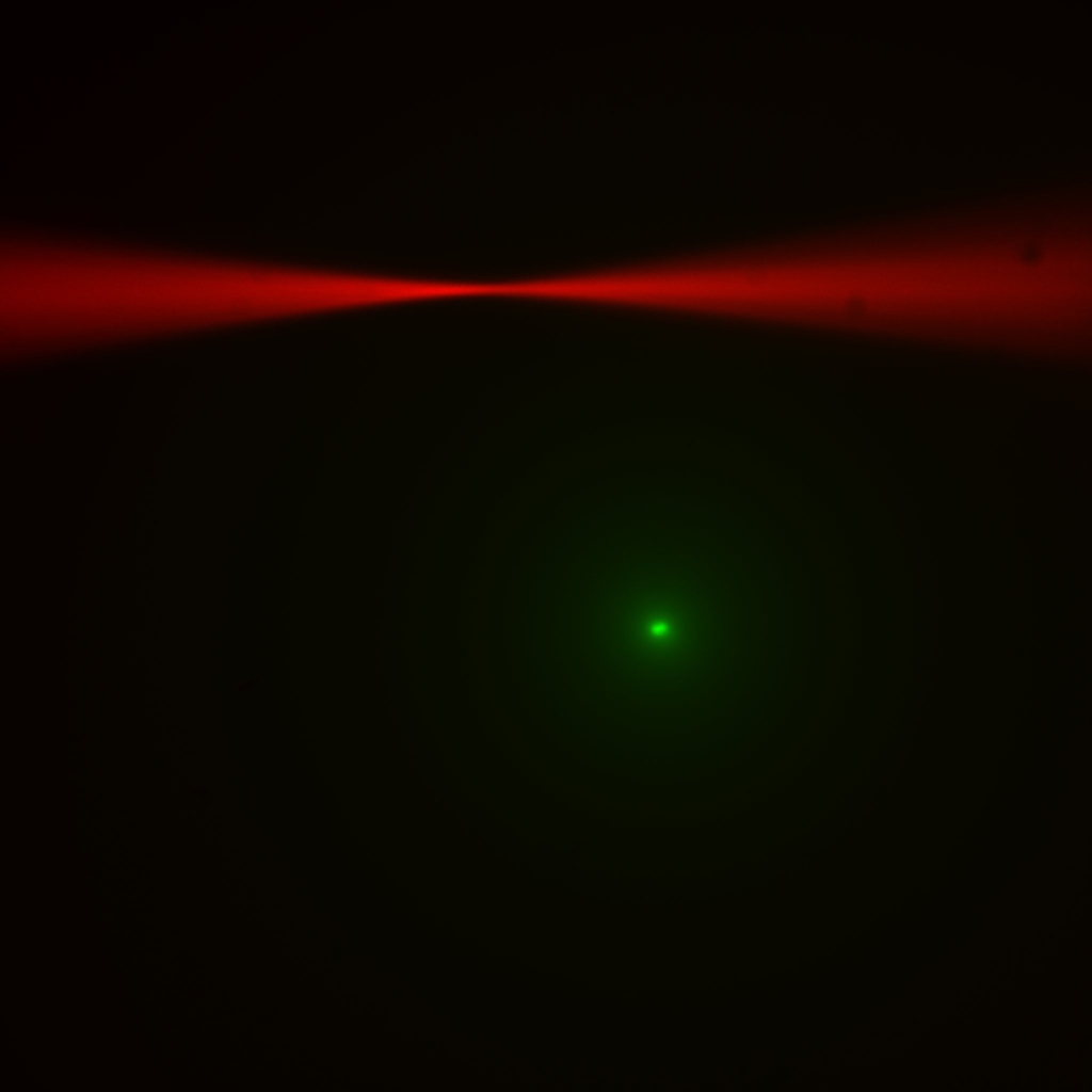 Figure 4: Open the scanner iris and observe the beam waist.
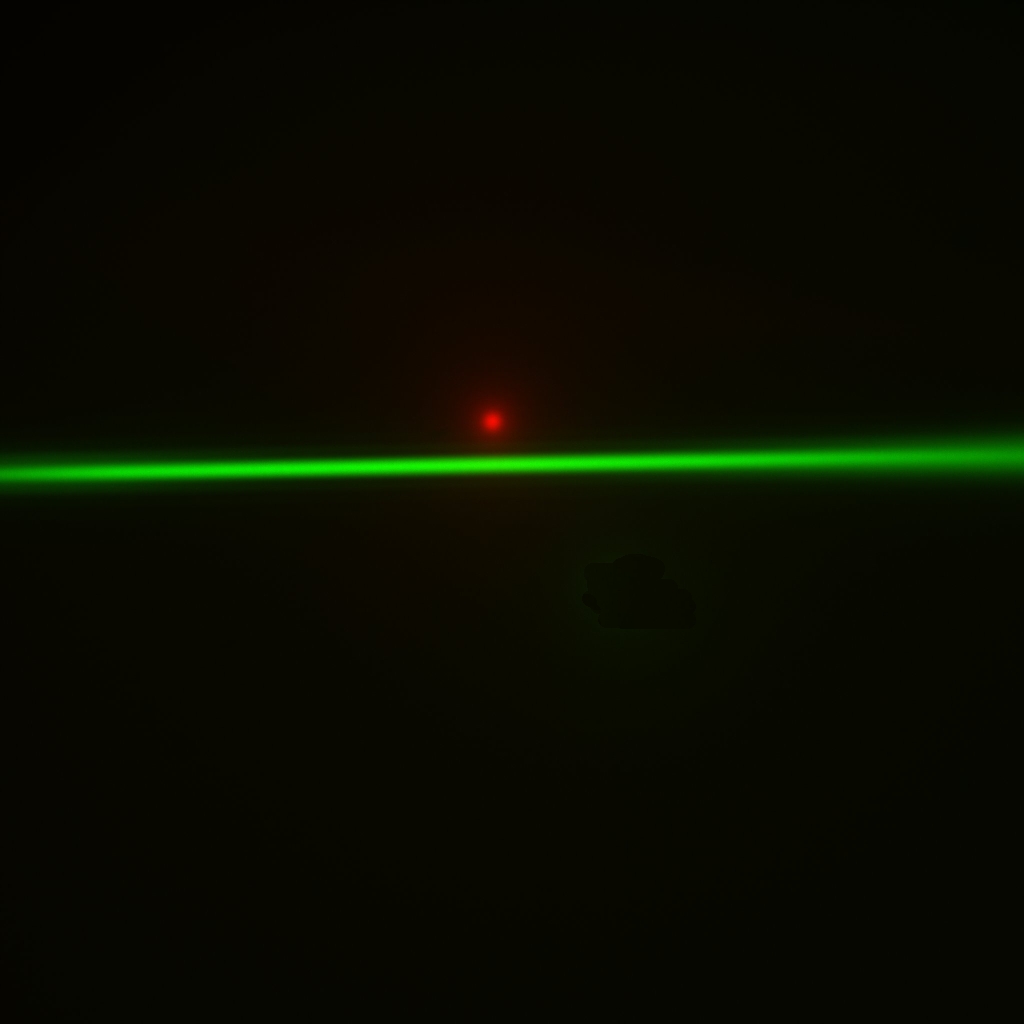 Figure 5: witch to the other beam and repeat the alignment of the pencil beam on the other side.
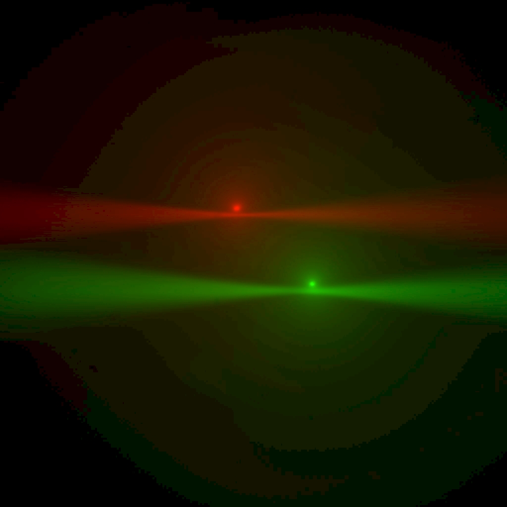 Figure 6: Now turn both beams on again and use the lateral objective adjuster to bring the red beam to the red spot and green beam to green spot. Notice when everything is in focus, the beam waist is near the epi-spot from the opposite-side beam. You can use this
effect to aid in co-focusing the objectives.
 Figure 7: Finally the steering mirrors for the
cameras (items 8 in Figure 1) are adjusted to bring the epi spot to the center of the camera frame. First on one
side and then to match on the other side.
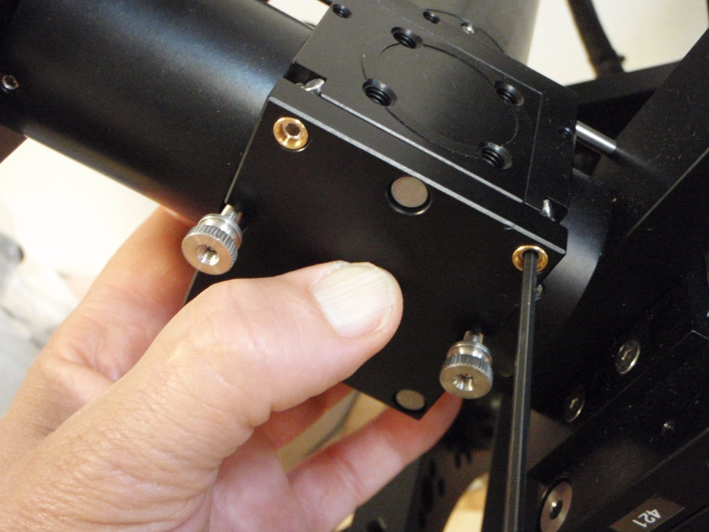 Figure 8: Adjusting the mirror steering screws.
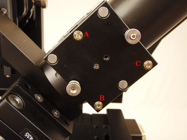 Figure 9: Use adjuster A alone, or B and C in tandem, to tilt beam in/out of focus plane. Use adjusters B or C alone, or in opposition, to tip beam horizontally to align parallel with the edge of the camera image.
Adjust dichroic mirror tilt
Verify that the the piezos and scanners are in their neutral positions everything at zero (use the MicroManger diSPIM plugin Navigation tab). Adjust the beam pointing to get the beams pointed exactly perpendicular to the field of view and exactly in the image plane. This was adjusted approximately previously in Section [sub:Adjust-dichroic-tilt]; now adjust it based on the camera images. Use the scanner iris to stop the beam down into a pencil beam. Use the MIM-CUBE-II mirror adjusters (see Section [sub:Adjusting-the-Mirror]) to make the beam horizontal and in-focus the entire length. Work with one beam at a time. It is not important that the imaging piezo is exactly at 0 at first, you will return to step [sub:Co-align-the-objectives] again after this step.
Check that the beam plane is coincident with the image plane by adjusting the imaging piezo (e.g. using the joystick knob) to make sure that the pencil beam comes in and out of focus uniformly. It may be helpful to use a LUT (false-color heat map) on a single-camera view to aid in judging uniformity. If the iris is fully opened to create a pronounced beam waist, then the waist position will remain unchanged as you focus and defocus using the imaging piezo. Adjust the mirror adjustors until the beam plane is coincident with the image plane; Figure [fig:Beam-steering-adjusters.] shows which adjustment screws to use.
After the tilt with respect to the image plane is correct, then adjust the mirror tilt to get the beam horizontal. The grid overlay in the Pattern Overlay plugin in Micro-Manager () can be helpful by providing reference lines. Confirm that the tilt adjustment did not tilt the beam relative to the image plane. See Figure [fig:Beam-steering-adjusters.] for which adjustment screws to use.
Adjust imaging mirrors
Using the mirror adjusters on the two camera mirror cubes, move the epi spot to the center of the camera image. The two sides should overlap in the center. See Figure [fig:Co-aligning-objectives]e) & f). You may need to repeat this step again several times as other adjustments slightly disturb this. The crosshair overlay in the Pattern Overlay plugin in Micro-Manager () can be helpful by marking the center of the image.
Check collimator focus
Open the iris completely to see the focus point; we want that to be in the center of the image. Equivalently, this corresponds to a maximum epi-spot intensity. Insert the fiber collimator focus tool in the opening in the side of the collimator and engage the lip on the lens mount. Turning the tool should change the focus point along the beam (if needed, slightly loosen the retaining set-screw on the opposite side). Only small movements should be needed. See Figure [fig:Focusing-the-fiber]. Adjust it so that the beam focus is at the center of the image.
The lens assembly can slip entirely out of the collimator housing if you loosen the set screw without the tool engaged; if that happens you will have to unscrew the fiber collimator from the scanner housing to put it back together. 3)
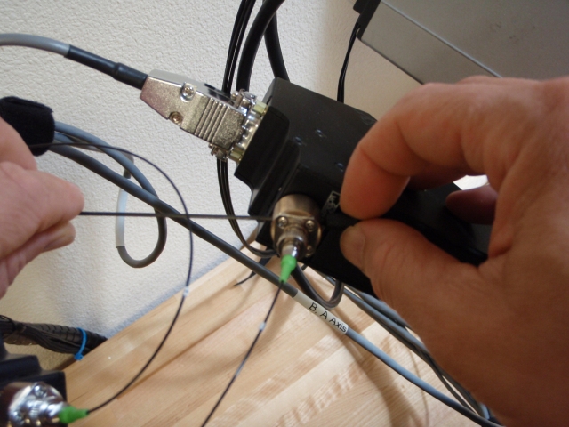 Figure 10: Focusing the fiber collimator to get smallest epi-illumination spot.
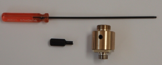 Figure 11: Collimator adjuster tools
Adjust scanner slice position offset
Usually it is possible to get the objectives co-focused with the piezos near their centered or 0 position. If you have achieved this you can skip the remainder of this step.
If it seems impossible to get the two objectives co-focused with the piezo positions near 0, you have two options: use a non-zero piezo offset or use a non-zero scanner slice position offset. If the sample of interest occupies most of the piezo range, only the later is viable. However, using a piezo offset is a simpler approach. In either case start with the objective bushings moved to a middle position that remains fixed.
Using a piezo offset is straightforward: an offset will be computed automatically by the piezo-scanner cross-calibration explained in Section [sub:Cross-calibrate-piezo]. Simply you will only need to use start and end points of the calibration curve that are not symmetric about 0.
To use a scanner slice position offset, the piezo-scanner cross-calibration explained in Section [sub:Cross-calibrate-piezo] will make the offset appear during imaging, but you should compensate for the offset by moving the imaging mirrors (Section [sub:Adjust-imaging-mirrors]) so that in the middle of the range the epi-spot is centered in the epi camera. Do this by setting the piezo to 0, moving the slice position until the beam is in focus, then adjusting the imaging mirror. Repeat for the other side. This should make it so that the epi spot is overlaid with the beam focus.