This is an old revision of the document!
Table of Contents
Assembly
The steps in this section are demonstrated in the following YouTube video: https://www.youtube.com/watch?v=TAgbr6IrTqw.
Attach the SPIM assembly to the microscope frame
The SPIM assembly is shipped separately and mostly assembled. The RAMM frame stand or the microscope mount assembly has two vertical arms on the back where 2 dowel pins each (total of 4) connect the microscope frame to the SPIM-MOUNT . Slide the complete SPIM assembly onto the dowel pins and fastened in place with the bolts provided (M8 thread with M6 Allen head). See Figure 1. If you need to set down the SPIM assembly, be careful not to rest it on the piezo objective movers (where the objectives will go) but instead tip it backwards and rest it on the arm and tube lenses to protect the piezos.
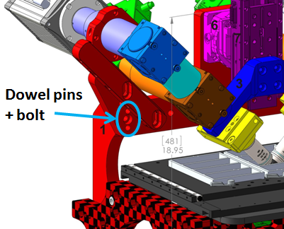 Figure 1: RAMM frame with SPIM assembly, showing location of dowel pins and bolts.
Once you have the SPIM assembly attached to the microscope frame, the next step is to add the scanners and cameras to the tube lenses using the C-mount adapters.
Attach the scanners
Locate the scanner tube lenses, C-mount adapters, and scanners. Attach the scanners to the C-mount adapters as shown in Figure [fig:Scanner-assembly]. Attach the tube lens assemblies to the lower MIM-CUBE-II ’s using a 2 mm Allen wrench to secure the three set screws to the adapter ring. Insert the C-mount adapter with scanner attached into the tube lens fitting and secure with the set screws1). Be sure the scanner assembly is aligned parallel / perpendicular to the MIM-CUBE-II.
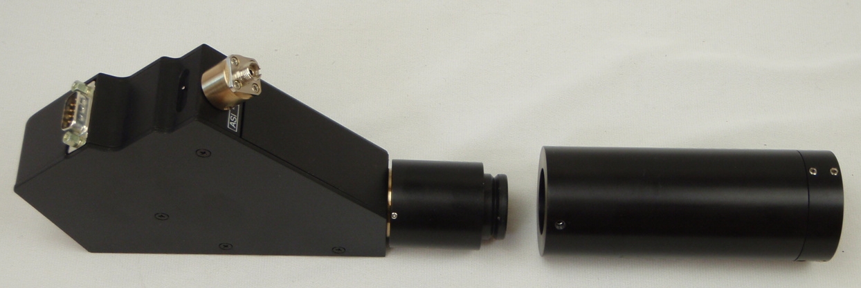 Figure 2: Scanner attached to C-mount adapter with tube lens assembly ready to be installed.
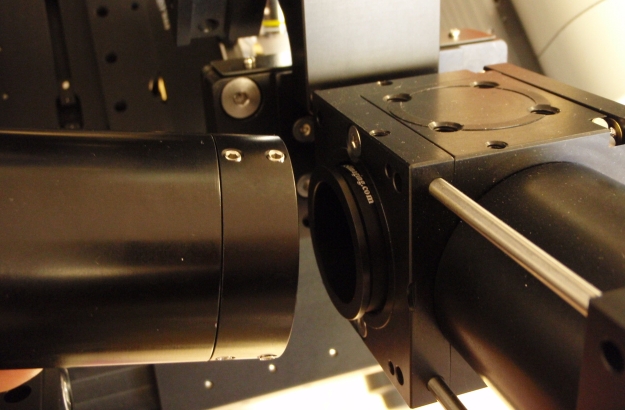 Figure 3: Tube lens assembly is attached to lower cubes on the microscope.
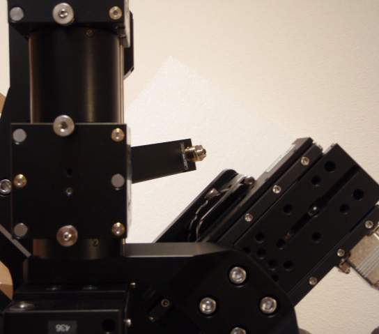 Figure 4: Scanner attached at C-mount with poor alignment
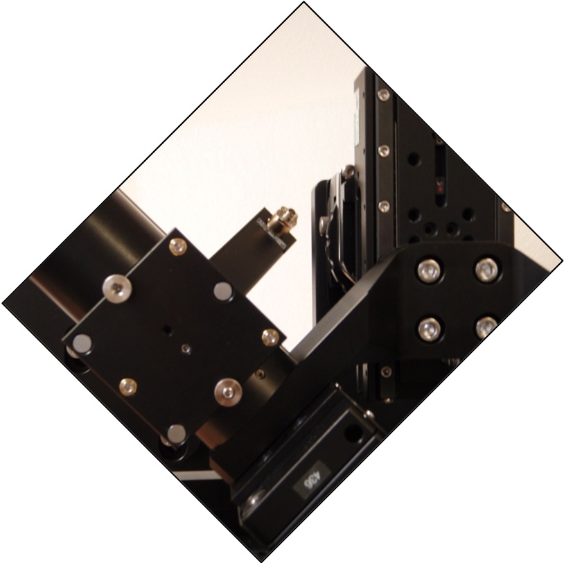 Figure 5: better alignment
The scanners should be attached such that the fiber connectors are facing upwards and in toward the center at a 45 degree angle as shown in Figures [fig:Scanner-assembly], [fig:Andor-Zyla-cameras], and [fig:PCO-Edge-cameras]. Be sure all of the set screws on the lens tubes, cubes, and C-mounts that hold the scanners are snug and the that scanners cannot wiggle around on the mount. After firmly securing the C-mount to the scanner, tilt adjustment is made by rotating the C-mount in the lens tube and securing with the set screws for the C-mount.
Attach the cameras
The camera tube lenses are fastened to the SPIM-MOUNT with a pair of ring clamps that clamp the tube lenses to the frame. The end of the lens tubes should come to within about 1mm from the mirror cube on the SPIM arm. This allows the entire objective pair assembly to be moved up and down for focus without needing to move the cameras. When the objectives are lowered into position for viewing a sample, the camera tube lenses assembly can be adjusted so that the tube lenses are centered on the mirror cube. Two M8 Allen head bolts hold the lens tube support arms to the frame. By loosening those bolts it is possible to adjust the position of the lens tubes to be centered on the mirror cube.
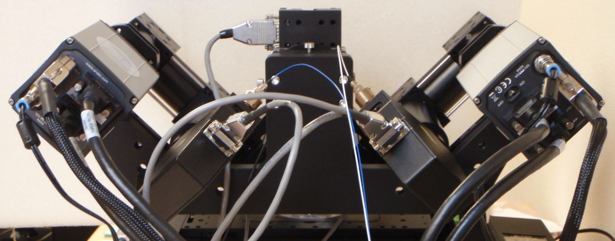 Figure 6: Scanners and Andor Zyla cameras installed in conventional orientation.
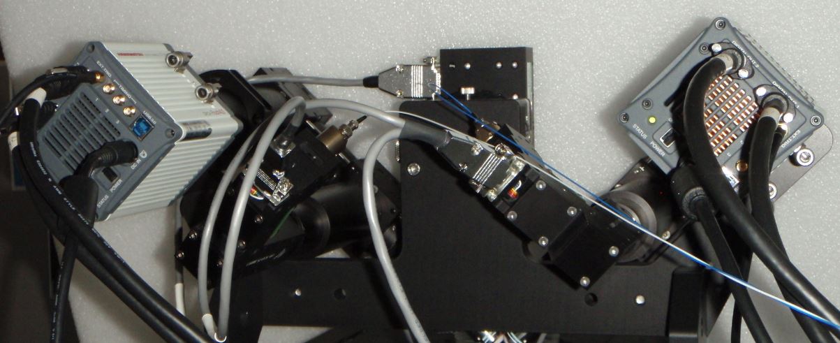 Figure 7: Scanners and Hamamatsu Flash4 cameras installed in conventional orientation.
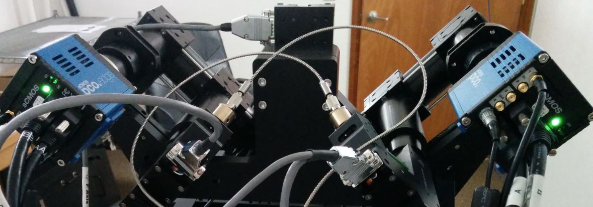 Figure 8: Scanners and PCO Edge cameras installed in conventional orientation.
Camera orientation
The user has a choice of camera orientation. Although other choices are possible, our convention2) is to have the image of the illuminating sheet laser beam appear horizontal with the laser coming from the right objective appearing as coming from the right side of the left-side camera image and vise versa for the opposite objective.3) Figure ## shows the Micro-manger MultiCam image of the light sheet lasers entering a dye solution when the cameras are positioned as recommended. 4)
For the laser to appear horizontally, the cameras need to be tilted at 45 degrees from vertical. Figures Figure 6, Figure 7, and Figure 8 respectively show Andor Zyla, Hamamatsu Flash4, and PCO Edge cameras oriented in the conventional way.
 Figure 9: Laser beams seen by cameras in conventional orientation. The green image is from the left-side camera and shows the beam from the right-side scanner entering from the right and eventually stiking the coverslip where it stops. The red image is from the right-side camera, shows the beam from the left-side scanner entering from the left. The bright spots are the epi-fluorescent excitation from the scanner on the same side as the respective cameras. The following statement will be understood after going though the alignment: the objective lateral alignment is perfect because the epi and beams exactly overlap, but the camera mirrors need to be adjusted slightly to put both epi spots in the image center.
Insert the objectives
The method for inserting the objectives was significantly simplified in the piezo mounting scheme introduced in early 2015. Older systems can be upgraded with the new piezo mounting scheme. The main benefit of the new scheme is eliminating the AOA objective adjuster, replacing it by a smooth linear stage, which greatly eases objective alignment. In the new scheme the piezos easily slide out of the arm for easy exchange and cleaning of objectives. The linear adjuster is fixed instead of being moved by the piezo, improving speed slightly. Finally, the bushings include teflon glides to keep them snug.
Refer to the appropriate section to insert your objectives.
With pre-2015 piezos
At one point ASI recommended screwing in the objectives one at a time, retracting the objective bushings fully to make space, and subsequently returning the bushings to the desired position. However, to lessen mechanical stresses on the piezo actuators, ASI now recommends assembling the objective with bushing and piezo objective mover (and lateral adjuster if present) separately from the microscope and then attaching it to the SPIM arm mount. This way the objective bushings do not need to be retracted beyond their normal travel, nor do you risk damaging the objective threads as you begin screwing it in slightly off-axis.
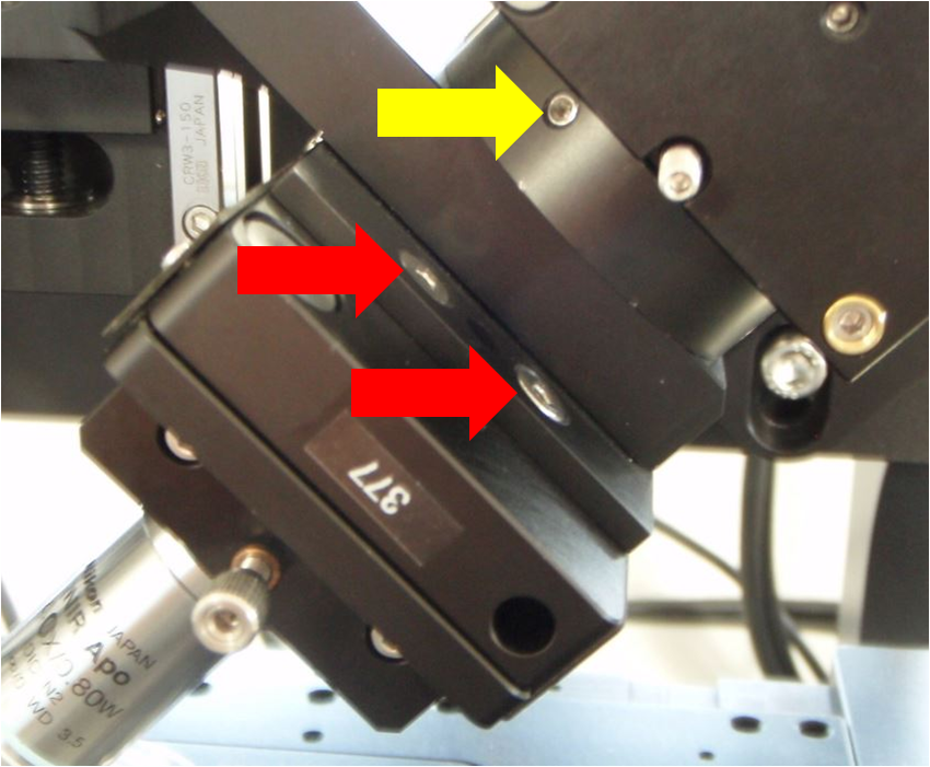 Figure 10: Close-up view of the screws holding the lower cube and rest of SPIM arm to the arm mount (yellow arrow) and also the screws holding the piezo objective mover to the SPIM arm mount (red arrows)
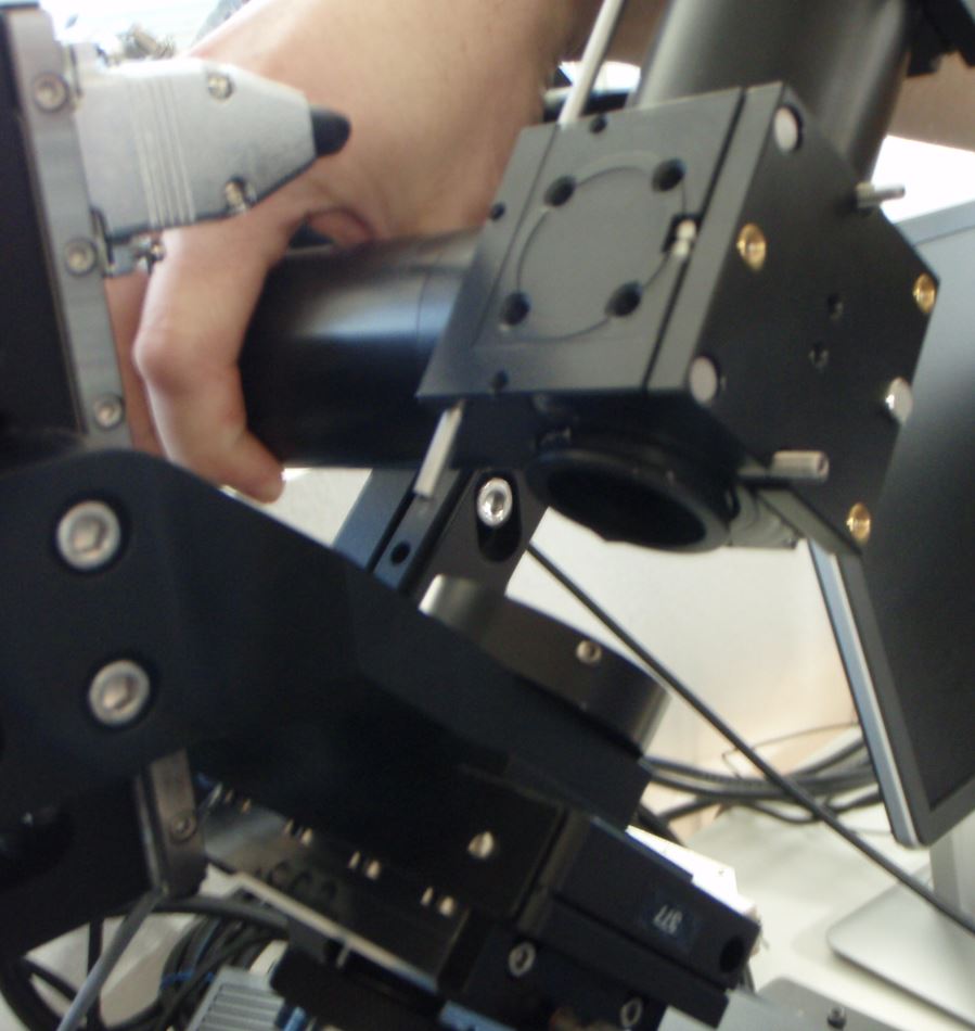 Figure 11: Separating the SPIM arm from the mount
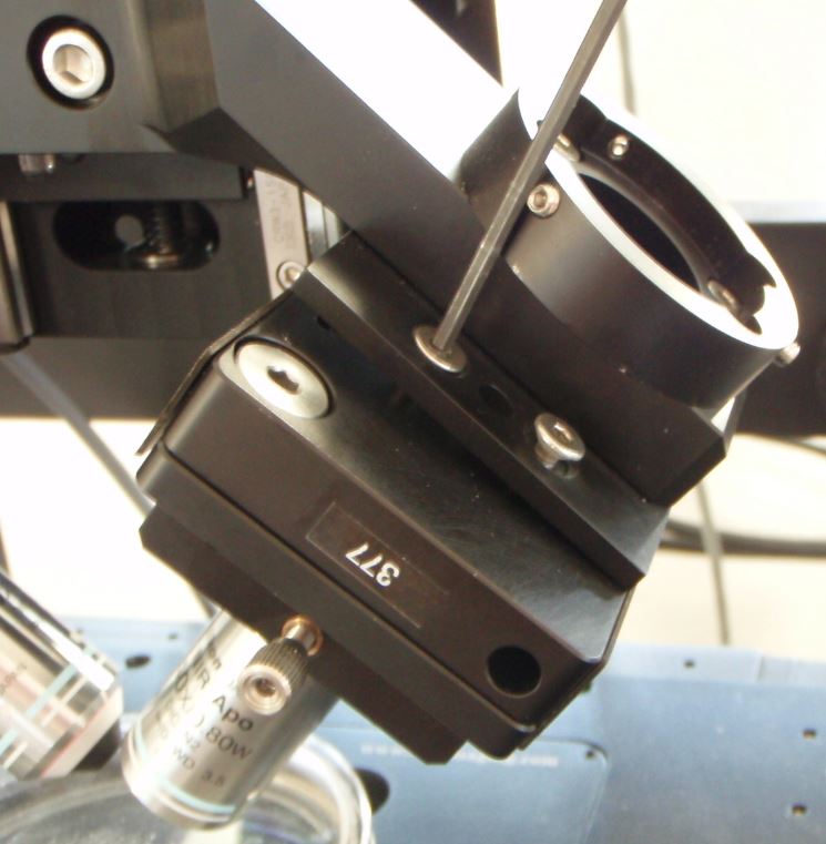 Figure 12: loosening or removing the screws holding the piezo objective mover to the SPIM arm mount.
Begin by removing one SPIM arm, intact, from the arm mount so you can access the screws connecting the piezo objective mover to the arm mount. It does not matter which side you remove. On the arm that you will remove, detach the electrical connector to the scanner along with its fiber optic cable. Loosen the three set screws around the ring connecting the arm mount to the bottom cube (labels 3 and 9 in Figure 1 of overview, or the screw marked with a yellow arrow in Figure [fig:Piezo-screw-closeup]a). After loosening the set screws you may need to pull slightly on the SPIM arm to disengage the support dowel between the lower cube and the arm mount. Note that the SPIM arm is heavy. Gently set it aside.
Next remove the piezo objective mover (APZOBJ) from the SPIM arm mount as shown in Figure 12. Loosen the four screws made accessible by removing the SPIM arm; these are the screws marked with red arrows in Figure 10. It is possible to fully remove the piezo objective mover and everything attached to it from the arm mount, but usually it is sufficient to simply loosen the 4 screws. Next, insert the objective into the bushing on the loosened piezo objective mover. Make sure the bushing is appropriately tightened; the nominal spacing between the objective bushings and the piezo or fixed mount is 5 mm on both sides, which means about 6 mm of bushing thread goes into the APZOBJ or PZMAG-AOA . The objective bushings (RAO-0004 and RAO-0023) thread into their respective piezo device or translatable mount in a smooth but snug fashion. Newer objective bushings have Teflon glides to keep them snug; the earlier version can be retrofitted with judicious use of Teflon (plumber’s) tape. ASI no longer recommends using the lock nut provided with early SPIM systems. The gap between the objective bushings and the piezo or fixed mount should be about 5 mm on both sides (about 2 mm if you have the lock nut installed).